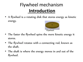
High Stored Energy Emergency Discharge Systems Overview
This presentation discusses the high stored energy emergency discharge systems for klystron modulators used in RFQ/DTL and MBeta applications. It covers the storage locations of energy in various capacitor banks, the components of the system, and safety measures. The content includes detailed diagrams and explanations of capacitor short-circuiting, grounding, and discharge mechanisms. Additionally, it highlights the discharge resistors and contactors used in the DC-link capacitors for safe energy dissipation.

Download Presentation

Please find below an Image/Link to download the presentation.
The content on the website is provided AS IS for your information and personal use only. It may not be sold, licensed, or shared on other websites without obtaining consent from the author. Download presentation by click this link. If you encounter any issues during the download, it is possible that the publisher has removed the file from their server.
E N D
Presentation Transcript
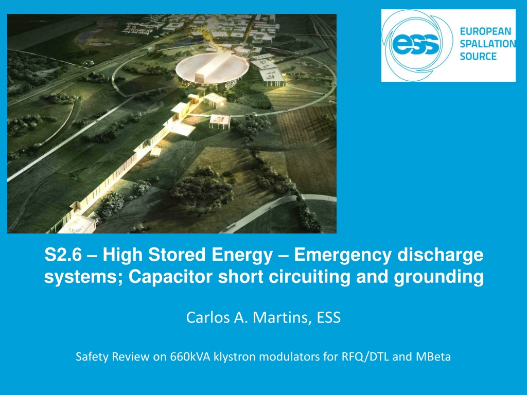
S2.6 High Stored Energy Emergency discharge systems; Capacitor short circuiting and grounding Carlos A. Martins, ESS Safety Review on 660kVA klystron modulators for RFQ/DTL and MBeta
High Stored Energy Where is the energy stored in the system? o 1)- Local capacitor bank of DC-link busses of AC/DC+DC/DC power stacks (Cdc A,B,C); o 2)- Main capacitor banks; o 3)- Local capacitor bank of H-bridge power stacks; KLYSTRON CABINET #1 HV CABLE 1 HV OIL TANK 10 AUX PS1 AUX PS4 DA+ FHB 1 1 DC/AC #1 LEM Ipulse 1 14 24 A2 13 23 A1 + - + - HVHF 1) CT 1+ CAPACITOR CHARGER #A 6 Transformer 1 HVL1 AUX TRANSF 13 23 14 24 RGsw 1 LEM DC-A Cbk 1 ROSS 1 230V ac DC/DC #A DRIVER DRIVER AC/DC #A 2) 400V CM Filter A LEM R-A (TRF 1) Lf R-A AUX POWER SUPPLY 24V AUX POWER SUPPLY 24V Rds A1 LEM CB-A Rds 1 Kds CBK Cdc A GSw KLYSTRON 1 OIL TANK Ccm CT 1- Rcb A Tcb A DRIVER DRIVER DRIVER DRIVER Lf S-A LEM S-A 600V HV Box 1 4Ccm DC/AC #2 Rds A2 Ldc A Lf T-A Lcm HVHF Kds A CT 2+ KLYSTRON 4Ccm FHB 2 HVL2 Transformer 2 E X T . U P S RGsw 2 LEM T-A KAC A Rds 2 HV CABLE CB AUX 2 DRIVER DRIVER Cbk 2 CBprechA 2 14 Ccm 5 3) CB AUX 1 RC 1 2 4 13 LEM Ipulse 2 8 A1 A2 Rpch CBdcPrechA Rpch CT 2- KprechA DA- CF 1 + - 7 9 HV Box 2 ROSS 2 13 14 23 24 RC 2 DC/AC #3 14 24 A2 13 23 A1 HVHF 1) CAPACITOR CHARGER #B CT 3+ 6 CF 2 FHB 3 DB+ Transformer 3 HVL3 KLYSTRON 2 OIL TANK LEM DC-B 230V ac DC/DC #B DRIVER DRIVER Cbk 3 AC/DC #B 2) LEM R-B Lf R-B CM Filter B Lfg - R Rds B1 LEM CB-B RGsw 3 Cdc B Rds 3 Kds CBK R Rcb B Ccm GSw CT 3- 10 KLYSTRON DRIVER DRIVER DRIVER DRIVER Lf S-B LEM S-B Lfg - S S EMC FILTER HV Box 3 HV CABLE 4Ccm 3 Lcm-out Tcb B DC/AC #4 Rf Rds B2 Lf T-B Ldc B Lfg - T Lcm HVHF Kds B CT 4+ T 3 4Ccm FHB 4 Transformer 4 LEM Ipulse 3 HVL4 LEM T-B 4Cfg 4Cfg RGsw 4 KAC B Rds 4 4Cfg DRIVER DRIVER CBprechB Cbk 4 Cfg Cfg Cfg 14 Ccm 5 Rb 3) ROSS 3 4 Rfg SDE 13 Rfg Rfg Rpch 8 Rpch A1 A2 CBdcPrechB CT 4- KprechB + - DB- 7 OF 9 HV Box 4 Cfgcm KLYSTRON 3 OIL TANK 1 13 14 23 24 DC/AC #5 14 24 A2 13 23 A1 HVHF AC fg CAPACITOR CHARGER #C 1) CT 5+ 6 SD FHB 5 DC+ Transformer 5 HVL5 LEM DC-C KLYSTRON DC/DC #C 230V ac DRIVER DRIVER Cbk 5 AC/DC #C 2) 3 LEM R-C CM Filter C Lf R-C 24 V Rds C1 LEM CB-C HV CABLE dc CT1 RGsw 5 4 Rds 5 Kds CBK Cdc C Rcb C Ccm GSw CT 5- 10 DRIVER DRIVER DRIVER DRIVER Lf S-C LEM S-C 4 LEM Ipulse 4 No Volt Coil HV Box 5 HV DIV 4Ccm DC/AC #6 Tcb C Rds C2 2 Ldc C Lf T-C Lcm HVHF Kds C CT 6+ ROSS 4 4Ccm FHB 6 MCB Transformer 6 HVL6 LEM T-C ON 3) RGsw 6 KAC C DRIVER Rds 6 Cbk 6 DRIVER DRIVER CBprechC 14 Ccm 5 KLYSTRON 4 OIL TANK OFF 4 13 8 CBdcPrechC Rpch A1 A2 Rpch KprechC CT 6- HV Box 6 Rgnd + - DC- 7 Arc Protec 9 13 14 23 24 11 PART I LV POWER CONVERSION STAGE
1)- DC link capacitors discharge resistors DC/DC AC/DC Resistors: - RDS A1, A2 (DC-link bus A); - RDS B1, B2 (DC-link bus B); - RDS C1, C2 (DC-link bus C); Discharge time below 50V: Discharge peak power: Rugged type: 0.8s 2 x 6.3 kW each resistor accepts 5x nominal power for 10sec 2 x For each DC-link bus: 2 x (47 / 1000V / 800W) in series CJT 800 series
1)- DC link capacitors discharge contactors DC/DC AC/DC Contactors: - KDS A (DC-link bus A); - KDS B (DC-link bus B); - KDS C (DC-link bus C); For each DC-link bus: LTC 100 type, 1-pole, NC Rugged type, railway applications
2)- Main capacitor bank discharge resistors Automatic discharge system For each main capacitor bank: 2 x (2 / 1000V / 10 shots 50kJ) in series; Discharge time below 50V: 1.2s Discharge peak power: 2 x 125 kW
2)- Main capacitor bank discharge contactor Automatic discharge system For each main capacitor bank: LTC 100 type, 1-pole, NC Rugged type, railway applications Peak current: 1000A, = 0.4s
2)- Main capacitor bank discharge resistors Manual discharge and grounding system For each main capacitor bank: 2 x (0.5 / 1000V / 1 shot 50kJ) in series; Discharge time below 50V: 0.3s Discharge peak power: 2 x 500 kW
2)- Main capacitor bank discharge contactor Manual discharge and grounding system For each main capacitor bank: 3 pole, 315 A Switch disconnectors type: OT315E12P Peak current: 1000A, = 0.4s
3)- H-bridge capacitor bank discharge resistors Manual and automatic system In case the fuse breaks, it is important to keep a discharge path for the H-bridge capacitor banks For each capacitor bank: - 1 Resistor, 22 /(One 4.5kJ shot per 5h)/1kV, type rod 708A, for the manual discharge circuit; - 1 Resistor, 22 /(One 4.5kJ shot per 5h)/1kV, type rod 708A, for the automatic discharge circuit; Type rod 708A; Do= 20mm; L= 70mm
Internal&External Fast Stops, Door Switches One Internal Fast Stop (Red button) is present near the control cabinet; One External Fast Stop is available for remote protection in the hard- wired control port (RF-LPS interface cable); Every door is equipped with a door switch; Internal Fast Stop (Red button) All these signals are amongst the most critical for personnel safety and are therefore treated the same way (SIL 3 level): Each signal is individually hard-wired to a safety PLC (ABB Pluto series), using wires placed in mechanical protective conduits; Whenever one or several of these signals are activated: the safety PLC de-energises the Under-Voltage Release (UVR) coil of the Main Circuit Breaker (MCB); Simultaneously, the safety PLC de-energises the coils of the capacitor discharge contactors (LTC 100), triggering their automatic discharge; Simultaneously, the safety PLC sends a signal to the central controller to bring the state machine to off state (switch off all IGBT s, contactors, etc.); Safety PLC (ABB Pluto)


- DC link capacitors’ discharge resistors")
- DC link capacitors’ discharge contactors")
- Main capacitor bank discharge resistors")
- Main capacitor bank discharge contactor")
- Main capacitor bank discharge resistors")
- Main capacitor bank discharge contactor")
- H-bridge capacitor bank discharge resistors")