Designing a 5V DC Power Supply Using IC 7805: Step-by-Step Guide
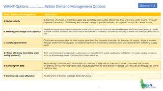
Design a 5V DC power supply using IC 7805 by selecting a regulator IC, transformer, diodes for the bridge, smoothing capacitor, and ensuring safety. The circuit includes an input transformer, rectifier circuit, filter, and regulator. Understand the importance of each component in the design process to create a stable 5V output. Utilize a general block diagram to design individual sections before assembling the complete circuit.

Designing a 5V DC Power Supply Using IC 7805: Step-by-Step Guide
PowerPoint presentation about 'Designing a 5V DC Power Supply Using IC 7805: Step-by-Step Guide'. This presentation describes the topic on Design a 5V DC power supply using IC 7805 by selecting a regulator IC, transformer, diodes for the bridge, smoothing capacitor, and ensuring safety. The circuit includes an input transformer, rectifier circuit, filter, and regulator. Understand the importance of each component in the design process to create a stable 5V output. Utilize a general block diagram to design individual sections before assembling the complete circuit.. Download this presentation absolutely free.
Presentation Transcript
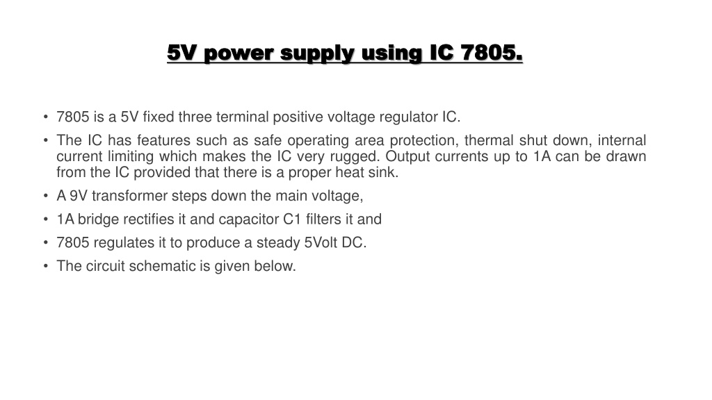
5V power supply using 5V power supply using IC IC 7805. 7805. 7805 is a 5V fixed three terminal positive voltage regulator IC. The IC has features such as safe operating area protection, thermal shut down, internal current limiting which makes the IC very rugged. Output currents up to 1A can be drawn from the IC provided that there is a proper heat sink. A 9V transformer steps down the main voltage, 1A bridge rectifies it and capacitor C1 filters it and 7805 regulates it to produce a steady 5Volt DC. The circuit schematic is given below.
The design of 5V DC power supply The input transformer The rectifier circuit The filter The regulator Circuit diagram of 5V DC power supply Step by step method to design 5V DC power supply Step 1: The selection of regulator IC Step 2: The selection of transformer Step 3: The selection of diodes for the bridge Step 4: The Selection of smoothing capacitor and calculations Step 5: Making the power supply safe
The design of 5V DC power supply The design of 5V DC power supply The design of any circuit begins with a well made general block diagram. It helps us to design the sections of the circuit individually and then at the end put them together to have a complete circuit, ready for use. The general block diagram for this project is given below. It is very simple. It has the following four main sub-blocks. The Transformer The Rectifier Circuit The Filter The Regulator
Block Diagram of Power Supply Block Diagram of Power Supply
The input transformer The input transformer A transformer is a device that can step up or step down voltage levels, following the law of conversation of energy. The question is, why we need it in our supply design? Well, depending on our country, AC coming to our home has a voltage level of 220/120 V. We need the input transformer to step down the incoming AC to our required lower-level i.e. close to 5V (AC). This lower level is further used by other blocks to get the required 5V DC. A transformer is a device that is used to step up or step down the AC voltages level, keeping the input and out power the same.
The rectifier circuit The rectifier circuit If you are thinking the transformer just stepped down the voltage to 5V DC. The stepped- down voltage is still AC. To convert it into DC, you need a good rectifier circuit. A rectifier circuit is the combination of diodes arranged in such a manner that converts AC into DC voltage. Without the rectifier circuit, it is not possible to have the required output 5V DC voltage.
The filter The filter The rectifier circuit converts the incoming AC to DC but it does not make it a pure DC. The output of the rectifier is pulsating and is called pulsating DC. This pulsating DC is not considered good to power up sensitive devices. The rectified DC is not very clean and has ripples. It is the job of the filter to filter out these ripples and to make the voltage compatible for regulation. A capacitor filter is used when we need to convert a pulsating DC into pure or to remove distortion from signal. A capacitor is a charge storing device. But actually, it can be best used as a filter. It is the most inexpensive filter for our basic 5V power supply design.
The regulator The regulator A regulator is the linear integrated circuit use to provide a regulated constant output voltage. Voltage regulation is very important because we do not need a change in output voltage when the load changes. An output voltage independent of the load is always required. The Regulator IC not just makes the output voltage independent of varying loads (outputs), but also from line voltage (input) changes. A regulator is the integrated circuit used to give a constant output voltage regardless of input voltage changes.
How does the 5V Power Supply work? How does the 5V Power Supply work? First, we are using a step-down transformer [Secondary rating 9Volt & 1 Amp] to step down 230V/ 110V AC supply to 9-Volt AC. Then we rectify the 9V AC to 9 V DC using a diode bridge rectifier [Full wave rectifier]. After the rectifier, we have used Capacitors to filter the ripple from the circuit and fed it to the input of the 7805 voltage regulator. 7805 regulates the 9 volt DC to 5 Volt DC and at the output of 7805 ic, we get constant 5 Volt DC output.
MULTISIM MULTISIM - - Schematic design of 5 V Regulated Power Supply Schematic design of 5 V Regulated Power Supply
Step by step method to design 5V DC power supply Step by step method to design 5V DC power supply Step 1: The selection of regulator IC The selection of a regulator IC depends on your output voltage. In our case, we are designing for the 5V output voltage, we will select the LM7805 linear regulator IC. In the design process, the next thing is, we need to know the voltage, current, and power ratings of the selected regulator IC. This is done by using the datasheet of the regulator IC. The following are the datasheet provided ratings and pin diagram for LM7805.
Step 1: The selection of regulator IC Step 1: The selection of regulator IC
Step 2: The selection of transformer Step 2: The selection of transformer The right transformer selection means saving a lot of money. We got to know, the minimum input to our selected regulator IC is 7V (See above datasheet values). So, we need a transformer to step down the main AC to at least this value. But, between the regulator and secondary side of the transformer, there is a diode bridge rectifier too. The rectifier has its own voltage drop across it i.e. 1.4V. We need to compensate for this value as well.
Step 2: The selection of transformer Step 2: The selection of transformer
Step 2: The selection of transformer Step 2: The selection of transformer This means we should select the transformer with a secondary voltage value equal to 9V or at least 10% more than 9V. From these points, for the 5V DC power supply design, we can select a transformer of current rating 1A and a secondary voltage of 9V. Why 1A current? Because the regulator IC has a current rating of 1A, meaning we cannot pass more current than this value. Selecting a transformer with a current rating more than this will cost extra money. And we don t need it.
Step 3: The selection of diodes for the bridge Step 3: The selection of diodes for the bridge
Step 4: The Selection of smoothing capacitor and Step 4: The Selection of smoothing capacitor and calculations calculations We need to calculate the proper capacitance value. It depends upon the output voltage and the output current. To find the proper value of capacitance, use the formula below: Where, Io = Load current i.e. 500mA in our design, Vo = Output voltage i.e. in our case 5V, f = Frequency i.e 50Hz In our case:
Step 5: Making the power supply safe Step 5: Making the power supply safe Every design must have a safety feature to protect it from burning. Similarly, our simple supply must have one i.e. the input fuse. The input fuse will protect our supply in case of overloading. For example, our desire load can handle 500mA. If in case our load starts to miss behave, there is a chance of burring of components. The fuse will protect our supply. A rule of thumb for selecting the fuse rating is, it must be at least 20% more than the load current.