Understanding the 1000-Hour Landing Gear Inspection for Comanches

The 1000-hour landing gear inspection for Comanches is crucial for compliance with ADs 77-13-21 and 97-01-01 R1. This maintenance activity, not preventive maintenance, should be overseen by an A&P mechanic and documented meticulously. The inspection involves various components and considerations beyond the scope of the ADs, highlighting the importance of proper maintenance to ensure aircraft safety and airworthiness.

Understanding the 1000-Hour Landing Gear Inspection for Comanches
PowerPoint presentation about 'Understanding the 1000-Hour Landing Gear Inspection for Comanches'. This presentation describes the topic on The 1000-hour landing gear inspection for Comanches is crucial for compliance with ADs 77-13-21 and 97-01-01 R1. This maintenance activity, not preventive maintenance, should be overseen by an A&P mechanic and documented meticulously. The inspection involves various components and considerations beyond the scope of the ADs, highlighting the importance of proper maintenance to ensure aircraft safety and airworthiness.. Download this presentation absolutely free.
Presentation Transcript
The 1000 hour Landing Gear Inspection for Comanches AD 77-13-21 AND AD 97-01-01 R1 SUBMITTED BY : DAVID SCHOBER 1
My Bio Just some info on me and my background. After High School I worked at various factory jobs and ended up putting myself through college working as a machinist. That s where I developed my skills in metrology. In college I got my A&P and a degrees in Aircraft Maintenance Engineering and Aircraft Maintenance Management. I got my A&P in 1977 and my IA in 1980. Was selected as an FAA Designated Airworthiness Representative in 2004. Was selected as an FAA Designated Engineering Representative in 2011. First solo in 1969, currently hold Commercial SEL, SES, MEL, Instrument Airplane, Glider, Flight Instructor Airplane Single and Multi engine, Instrument Airplane, Glider. I am by no means a Comanche Expert having only owned my PA-30 for a year. 2
1000 Hr Gear Inspection The inspections outlined are required by AD 77-13-21 and AD 97-01-01 R1. All work for compliance with these ADs is MAINTENANCE not Preventive maintenance. The work must be performed or supervised by an A&P and documented in the aircraft records per 91.417 All tools used to make Airworthiness Determinations should be calibrated with traceability back to NIST standards. Prior to any disassembly take pictures of EVERTHING! While the existing assembly may not be correct, they will certainly help in the reassembly process. ALWAYS consult the Maintenance Manual and the Parts Catalog to help in identifying the Correct way for things to go together. Unfortunately the Maintenance Manual can be hard to follow at times. 3
What the 1000 Hr Gear Inspection doesn t include The AD requirements listed on the prior slide do not inspect the entire landing gear system! Other things to consider: Compliance with the two ADs referenced will not result in a complete landing gear overhaul! If a complete overhaul of the gear is desired there is a lot more work involved. There are multiple other bolts, bushings and components that are not included in the inspections required by the ADs. All of them need to be checked! Landing gear alignment should also be checked at this time. Verify the proper hardware is installed in the scissors! Landing gear rigging is not addressed in the ADs. ANY time the actuating components of the gear are disassembled, the ENTIRE gear system needs to be rigged from scratch! There are special tools for rigging that should to be used! The Comanche Gear Setting tool is almost a MUST HAVE. (Picture on slide 34) The Landing Gear/Transmission needs to be inspected and serviced. End play for the transmission is a maximum of .015 . Mine was over .250 when I pulled it out! IF the end play exceeds .015, the transmission needs to be overhauled or replaced. 4
What the 1000 Hr Gear Inspection doesn t include The conduit assemblies should be inspected as should all the rod end bearings. If the conduits haven t been replaced they are likely ready to be. 5
What the 1000 Hr Gear Inspection doesn t include There is a Landing Gear retraction torque check (Paragraph 7-49 in the Twin Manual). It would be a good idea to perform this check both before and after any maintenance is done on the landing gear retraction system. If you have a clamp on AMP meter that measured DC Amps, it would also be a good idea to measure the AMPS required for both extension and retraction. While the airplane is on jacks is a good time to actually practice your EMERGENCY EXTENSION technique. WARNING: DO NOT let the gear free fall during this exercise! Have someone under the airplane to catch a main gear and slowly lower it after the first half travel. Allowing free fall is what can cause cracks in your side brace studs. 6
AD 77-13-21 This AD has two Paragraphs of importance. The 1000 hr inspection is covered in Paragraph (a). Paragraph (a) references page 3 of Piper SL 782A. Piper SL782 has been updated to Revision B, so if complying with SL782B you are doing this inspection in accordance with an AMOC, not in accordance with the AD. Paragraph (c) is what tells you to repeat the inspection called out in (a) each 1000 hrs. The AD and SL requires inspection of multiple internal and external diameters, internal and external threads and rod end bearing wear. Any items beyond published limits require replacement. Set up a sheet where you can record all the dimensional checks. Use this to determine what parts are serviceable and what parts need to be replaced. 7
Inspection Most inspection items are measuring down to .001 however there are a few items that measure down to .0005 Inspection tools for measuring must have the ability to measure to the level of precision identified. Vernier calipers and digital calipers only have the ability to accurately measure to .001 Micrometers can either be .001 or .0001 , Micrometers with .0001 capability would be appropriate for this inspection. For measuring rod end wear, the limit is .005 so the dial indicator needs to have a capability of reading .005 or smaller increments. An indicator with travel and .001 measuring capability is more than sufficient. 18
Inspection The largest measurement for the inspection is .563 so everything can be measured with a 1 Micrometer and a set of small hole gages and one telescoping gage. The OD threads can be measured with thread wires (not easy for someone not used to doing it). The OD threads can also be measured with Ring Gages (I don t have these pictured in this presentation). The ID threads need to be measured with a thread plug gage. (I don t have that pictured in this presentation) The rod end wear is measured with a Dial Indicator 19
Inspection Plug gages can be used for the inspection but it is not the preferred methods. With plug gages you can t check for out of round conditions. The bushings in our gear do not wear evenly around the circumference so plug gages will not detect an oversized condition with an out of round hole (Egg shaped or oval) in the bushing. Bushing wear is not even in all directions and this causes the out of round condition. Tolerances in the SL are for the largest dimension within the hole. Plug gages can be used to detect oversized parts quickly without taking actual measurements, but any parts that show good with the plug gages should be measured to detect out of round conditions to ensure they are actually within tolerance. 20
Inspection, Dial Indicator (.001X 1 travel) 22
Using the tools Learning to measure with a micrometer is relatively easy. Visit this site or search for how to read a micrometer How to Read a Micrometer - Beginner's Guide - Machinist Guides Small hole gages (10) Very best way to measure small holes with Starrett S831, S829 Gauges, for a reasonable cost... YouTube Telescopic gages (10) Telescopic gauges, how it's made and how they're used + comparing 3 brands YouTube Measuring threads (10) SHOP TIPS #183 Measuring Threads -3 Methods tubalcain YouTube NOTE: In the video above the ring gage was dropped. : In the video above the ring gage was dropped. Any time a calibrated tool is dropped it needs to be recalibrated! needs to be recalibrated! Any time a calibrated tool is dropped it 27
Measuring parts For each bushing or bolt measured, it the measurement should be checks in multiple places radially and lengthwise. For holes, use the largest measurement. For bolts or OD measurements use the smallest measurement. Practice using the tools until you can take multiple measurements of the same part and consistently get the same results. Most micrometers will have a slip clutch or click type clutch. Use it to get consistent results. Never bring the anvils of a micrometer together! 28
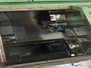
You measured everything, now what? Once everything is measured determine what parts need to be replaced and what can be reused. Most bushings that get replaced will be undersized and need machining after installation (and measuring again to ensure you didn t machine it oversized) Most of the bushings installed in aluminum pieces will require heat (and possibly cold) to remove the bushing without destroying the part it is inserted into. These parts are EXPENSIVE and some are hard to find! If you don t know what you are doing, bring it to someone that does! Heat in the form of an oven or heated oil bath (deep fat fryer works) and dry ice or liquid nitrogen for cold are the typical methods to heat and cool. Use appropriate PPE. You may need to make tools to hold the part or mandrels to push the old bushing out and new bushing in. Having access to a lathe and milling machine prior to starting is a good idea. 30
Installing new bushings Measure the OD of the bushing and the ID of the item the bushing is being inserted into. You may find that the housing that the bushing needs to be insered into is oversized and bust be replaced or have some approved repair . Heat the aluminum parts (be mindful of critical temperature (not over 200 degrees C) for aluminum). Jig the part and use a press or other tool that will maintain alignment to remove the bushing. DO NOT USE A HAMMER! Install the new bushing by reversing the removal and again use heat and cold. Once in place measure the new bushing ID to see if it is in tolerance. If undersized, obtain appropriate reamers to ream it to size using cutting oil. Use fixtures and a drill press or Bridgeport to ream the bushing to size (actually bring it about .0001 to .0002 undersized, then get a hone to hone it to size (again properly fixtured). 31
Installing new bushings As previously stated, parts are expensive. Destroying some of these parts could cost 10s of thousands of $ to replace! Improper use of reamers could result in oversized bushings and the need to replace them again! After reaming and honing, measure each bushing again to ensure it is within tolerance. Now that the bushings are all done, it is a good time to also comply with AD 97-01-01 Revision 1 and have the landing gear studs magnafluxed or florescent penetrant inspected. Measure before sending for magnaflux or FPI! If they are undersized you will need to replace them. This is also a 1000 hr requirement so it brings both inspections into alignment. 32
Bushings replaced and new bolts are here, now what? Once all the bushings requiring replacement have been replaced and machined to size it is time to reassemble the gear. Assume that the entire landing gear needs to be rigged! Do not rely on ANY prior rigging Do not rely on ANY prior rigging. Check the end play in your landing gear transmission (.015 maximum). Trying to rig with this end play out of spec will result in improper gear rigging and possible gear collapse. It is much better to rig the gear with the tool than with the gear motor. The tool can be made from a piece of square AL tubing with a hole at one end and slot at the other. The C/L of the hole and slot need to be 10.875 as this is a critical dimension for rigging the gear. 33
Bushings replaced and new bolts are here, now what? Part B of AD 77-13-21 requires replacement of the gear bungees each 500 hours or 3 years. Now is a good time to do this as well even if it isn t time. Recommendations are to replace these every year if the airplane is outside and every 2 years if hangered. Be sure the rollers for the bungees actually spin. Hans Neubert did research on Bungee longevity and there are 2 Comanche Zooms that he presented on the gear system. Go back and watch them for more info. There is also a CD that he produced covering this inspection and I recommend watching it prior to doing the inspection. The Service Manual recommends replacing the main gear assist springs when the bungees are replaced, so this is a good time to replace them as well. Be sure the swivels that attach the springs are free to swivel! 35
Now what? continued While talking about springs, the nose gear down lock springs need to be inspected for corrosion, wear and proper tension (45 +- 5 lbs when extended to 4 when measured at the inside of the loops). Any corrosion on these springs is cause for rejecting them. Be careful with replacement springs, Univair sells the same part number spring but it has been reported that the Univair springs don t meet the 45 lb tension requirement. When rigging the gear, each leg needs to be disconnected from the retraction mechanism and rigged independent of the others. This is the only way to accurately set the preload for the down lock (over center) setting. Unfortunately the Maintenance Manual does a poor job of describing the rigging process. The Comanche Gear book for replacing the conduits has a much better description. (Matts contribution to Comanche owners will truly be missed) Be sure to have the bolt that holds the spring swivel for the main gear pointed in the correct direction. Use a set of vice grips padded with duct tape or other soft surface to pull the swivel into place to hook it up. The bolt goes in from front to back. If reversed the threaded end will score the main spar! Make up bullets (bolts ground down to a point) to aid in alignment and insertion of the bolts. 36
The job is not finished until the paperwork is completed Log book entry should look similar to this: Landing gear inspected in accordance with AD 77-13-21 paragraph (a), AMOC dated September 26, 2008 and Piper SL 728B. Replaced the following components on the nose gear . . ., on the left main gear . . . And on the right main gear . . . Following inspection and part replacement the landing gear was rigged in accordance with section . . . Of the (PA- 24 or PA-30/39) service manual. This inspection is next due at XXXX hours total time. If you replaced the bungees, add Replaced bungess in accordance with AD 77-13-21 paragraph (b), next due at YYYY (500 hours from now) or ZZ/ZZ/ZZ (three years from now). If you replaced the springs, also note that. Main gear side brace studs were inspected in accordance with AD97-01-01 R1 paragraph (a)(1), inspection was done using (Florescent Penetrant/Magnaflux) method (or (Left/Right/Both)Side Brace stud(s) was/were replaced with part number YYYYY per paragraph (a)(1)). Following inspection landing gear was rigged as noted in entry for AD 77-13-21 above. This inspection is next due at XXXX hours total time. 37
Questions? Contact Info: David Schober 10919 Green Valley Rd. Union Bridge, MD 21791 240-409-4896 n14ky@aol.com PA-30 Serial 30-1307 N55RD PA-16 Serial 16-13 N5211H 38


")