2D and 3D Graphics Clipping Techniques
Explore the concepts of 2D and 3D clipping in computer graphics, including point, line, and polygon clipping algorithms like Sutherland-Hodgeman. Learn about the Weiler-Atherton algorithm for non-convex polygons and dive into 3D viewing techniques and projection methods.

Download Presentation

Please find below an Image/Link to download the presentation.
The content on the website is provided AS IS for your information and personal use only. It may not be sold, licensed, or shared on other websites without obtaining consent from the author. If you encounter any issues during the download, it is possible that the publisher has removed the file from their server.
You are allowed to download the files provided on this website for personal or commercial use, subject to the condition that they are used lawfully. All files are the property of their respective owners.
The content on the website is provided AS IS for your information and personal use only. It may not be sold, licensed, or shared on other websites without obtaining consent from the author.
E N D
Presentation Transcript
CS552: Computer Graphics Lecture 8: 2D Clipping
Recap 2D Clipping Point and Line Clipping Cohen-Sutherland Line Clipping Algorithm Polygon clipping Sutherland-Hodgeman Polygon Clipping
Objective After completing this lecture the students will be able to o Explain the issues with Sutherland-Hodgeman o Explain generalized polygon clipping technique o Solve numerical problems
Problems with Sutherland-Hodgman What if you clip these?
Weiler-Atherton Algorithm When we have non-convex polygons then the algorithm above might produce polygons with coincident edges This is sometimes OK for rendering but is not for other applications (e.g. shadows) The Weiler-Atherton algorithm produces separate polygons for each visible fragment
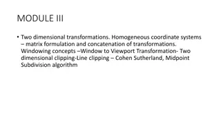
Objective After completing this section the students will be able to o Classify different projection techniques o Explain 3D Viewing pipeline o Transform 3D coordinate systems
Introduction Each object in the scene is typically defined with a set of surfaces They form a closed boundary around the object interior We may also need to specify information about the interior structure of an object Ultimately project a specified view of the objects onto the surface of a display device Additional routines are there to visualize a 3D scene
Projection We can choose different methods for projecting a scene onto the view plane. Parallel Projection o Project points on the object surface along parallel lines o Used in engineering and architectural drawing store present an object o A set of views that show accurate dimensions of the object
Projection Perspective projection o Project points to the view plane along converging paths o Objects farther from the viewing position : appear small o Objects of same size nearer to the viewing position: appear large o More realistic scene
Projection Orthographic Perspective
Types of Projection Projection Perspective Parallel One point Two point Three point Orthographic Oblique Multiview Axonometric General Isometric Dimetric Trimetric Cavalier Cabinet
Classical Viewings Hand drawings : Determined by a specific relationship between the object and the viewer.
Viewing Coordinates Generating a view of an object in 3D is similar to photographing the object. Whatever appears in the viewfinder is projected onto the flat film surface. Depending on the position, orientation and aperture size of the camera corresponding views of the scene is obtained.
Specifying The View Coordinates xv For a particular view of a scene o First we establish viewing- coordinate system. yv yw zv P0=(x0, y0, z0) A view-plane (or projection plane) is set up perpendicular to the viewing z-axis. xw zw World coordinates are transformed to viewing coordinates Then viewing coordinates are projected onto the view plane.
Specifying The View Coordinates To establish the viewing reference frame, o We first pick a world coordinate position : view reference point. This point is the origin of the viewing coordinate system. E.g. consider a point on an object o This point as the position where we aim a camera to take a picture of the object.
Specifying The View Coordinates Select the positive direction for the viewing z-axis, and the orientation of the view plane, by specifying the view- plane normal vector, N. yv xv xv yw zv N P0 Choose a world coordinate position P and this point establishes the direction for N. P xw zw OpenGL establishes the direction for N using the point P as a look at point relative to the viewing coordinate origin.
Specifying The View Coordinates Finally, choose the up direction for the view by specifying view-up vector V. yv xv V yw zv This vector is used to establish the positive direction for the yv axis. N P0 P The vector V is perpendicular to N. xw zw Using N and V, we can compute a third vector U, perpendicular to both N and V, to define the direction for the xv axis.
Specifying The View Coordinates To obtain a series of views of a scene , Keep the the view reference point fixed Change the direcion of N. This generate views as we move around the viewing coordinate origin.
Transformation From World To Viewing Coordinates It is equivalent to yv xv transformation that yw zv superimpoes the viewing reference frame onto the world frame using the translation and rotation. x w zw
Transformation From World To Viewing Coordinates First, we translate the view reference point to the origin of the world coordinate system yv xv yw zv x w zw
Transformation From World To Viewing Coordinates Second, apply rotations to align the yw xv, yv and zv axes with the world xw, yw yv yv and zw axes, xv zv respectively. x xv zv w zw
Transformation From World To Viewing Coordinates If the view reference point 1 0 0 x is specified at word 0 position (??,??,??), this point is translated to the 0 1 0 y 0 = T 0 0 1 z world origin with the 0 translation matrix ?. 0 0 0 1
Transformation From World To Viewing Coordinates The rotation sequence requires 3 coordinate-axis transformation depending on the direction of N. 1 0 0 0 0 0 Cos Sin = R x 0 0 Sin Cos First we rotate around xw-axis to bring zv into the xw -zw plane. 0 0 0 1
Transformation From World To Viewing Coordinates 0 0 Cos Sin Then, we rotate around the world 0 1 0 0 = R yw axis to align the y 0 0 Sin Cos zw and zv axes. 0 0 0 1
Transformation From World To Viewing Coordinates The final rotation is 0 0 Cos Sin about the world zw 0 0 Sin Cos = R axis to align the yw z 0 0 1 0 and yv axes. 0 0 0 1
Transformation From World To Viewing Coordinates The complete transformation from world to viewing coordinate transformation matrix is obtaine as the matrix product = M R R R T wc, vc z y x What if the rotation angles are not given ?
0 2 4 6 Transformation From World To Viewing Coordinates: An Example For 2d System y P=(5,5) =300 P0=(4,3) x 0 2 4 6
Transformation From World To Viewing Coordinates: An Example For 2d System 0 2 4 6 Translation: y 1 0 4 = T 0 1 3 P 0 0 1 =300 x P0 2 4 6
Transformation From World To Viewing Coordinates: An Example For 2d System 0 2 4 6 Rotation y . 0 866 5 . 0 0 = R 5 . 0 . 0 866 0 y 0 0 1 P x 2 4 6 P0
Transformation From World To Viewing Coordinates: An Example For 2d System New coordinates . 0 866 5 . 0 0 1 0 4 = M 5 . 0 . 0 866 0 0 1 3 .vc wc 0 0 1 0 0 1 ' . 0 866 . 0 500 . 4 964 5 . 1 866 x . 1 = = ' . 0 500 . 0 866 . 0 598 5 232 y 1 0 0 1 1 1
Transformation From World To Viewing Coordinates: An Example For 2d System 0 1 2 3 Alternative Method = n . 0 ( 866 . 0 500 ) y = v ( . 0 500 . 0 866 ) . 0 866 . 0 500 0 P = R . 0 500 . 0 866 0 n v 0 0 1 =300 x 1 2 3 P0 = x R T x '
Projections Once WC description of the objects in a scene are converted to VC we can project the 3D objects onto 2D view-plane. Two types of projections: o Parallel Projection o Perspective Projection
Parallel Projections Coordinate Positions are transformed to the view plane along parallel lines. View Plane P2 P 2 P1 P 1
Parallel Projections Orthographic parallel projection o The projection is perpendicular to the view plane. Oblique parallel projecion o The parallel projection is not perpendicular to the view plane.
Thank you Next Lecture: Projection Geometry