3D Forward and Back Projection for X-Ray CT Using Separable Footprints
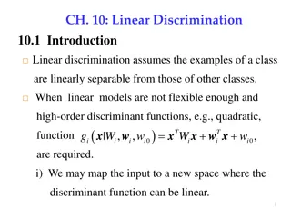
This project focuses on developing a surgeon-friendly user interface to simulate fluoroscopic views using Digitally Reconstructed Radiographs (DRRs). It aims to reduce time consumption, radiation exposure, and user variability by generating optimal views through forward-projection imaging techniques. The paper selection discusses novel approaches for 3D forward and back projections in X-Ray CT using separable voxel footprint functions, optimizing accuracy and computational efficiency.

Download Presentation

Please find below an Image/Link to download the presentation.
The content on the website is provided AS IS for your information and personal use only. It may not be sold, licensed, or shared on other websites without obtaining consent from the author.If you encounter any issues during the download, it is possible that the publisher has removed the file from their server.
You are allowed to download the files provided on this website for personal or commercial use, subject to the condition that they are used lawfully. All files are the property of their respective owners.
The content on the website is provided AS IS for your information and personal use only. It may not be sold, licensed, or shared on other websites without obtaining consent from the author.
E N D
Presentation Transcript
3D 3D Forward and Back Forward and Back- -Projection for X X- -Ray CT Using Separable Ray CT Using Separable Footprints Projection for Footprints 04/21/16 Group 5: Seung Wook Lee Mentor: Dr. Jeff Siewerdsen Dr. Matthew Jacobson, Dr. Tharindu da Silva, Dr. Joseph Goerres
Project Overview Goal: Surgeon-friendly User Interface (UI) to simulate fluoroscopic view of mobile C-arm Fluoro-hunting : - Process to find an optimal fluoroscopic view - Time-consuming, more radiation exposure to both patients and physicians, physically cumbersome, safety issues. Solution: Digitally Reconstructed Radiograph (DRR): - Generate forward-projection image of preoperative CT data - Use DRR to find the most optimal view Advantages - Less time consuming - Less radiation exposure - Less user variability
Paper Selection Long, Yong, Jeffrey A. Fessler, and James M. Balter. "3D Forward and Back-Projection for X-Ray CT Using Separable Footprints." IEEE Transactions on Medical Imaging IEEE Trans. Med. Imaging 29.11 (2010): 1839-850. Web. Paper: Proposes two new approaches for 3D forward and back projections by approximating a voxel footprint function as a 2D separable function. Reduce computational burden by simplifying integration of the footprint functions Our project: Generate DRR forward projection Possible implementation for more accurate DRR generation (as a future work) *Footprint Function: projection of a basis function (i.e. cubic voxel, etc)
Background Iterative statistical methods for 3D CT reconstruction Better image quality/ reduce dose than conventional Computationally heavy: bottleneck in iteration of forward/back projections Forward/backprojection per iteration Many studies with compromise b/t complexity and accuracy Evaluating integrals of footprint fn. over detector cell / Exact calculation of footprint function expensive
Background: Cone-Beam Geometry Cone-Beam (CB) system with flat detector : source position angle from y axis (s, t): detector coordinate p0, p1: source / projection point ? : Direction vector Ds0 : Source-rotation center distance D0d : Rotation center-detector distance ?: Azimuthal angle of a ray ?: Polar angle of a ray p1 z p1 ? y ? y x z p0 p0
Background: Cone beam projection Discretized object described by basis function ?0? superimposed on N1xN2xN3 Cartesian Grid: :Grid spacing. c n :center of nth basis function where ? = ?1,?2,?3 (???? ??????????) Basis function ????,?? = ????,??;? ?(?) ? Projection y of a 3D discretized object f(n) on detector (sk,tl): sum of blurred footprint * value Blurred footprint F: 2D convolution of q/h q: footprint function of nth basis on (s,t) with angle h: shift-invariant 2D blur function CB projection footprint function of nth basis on (s,t) with proj. angle : forward projection - Computationally expensive
Alternative approach: approximate footprint Simulated flat-detector CB geometry Exact Footprint functions computed for voxels centered at 3 different places Origin (left) (100, 150, 15), = 0 (mid) =2.1 (93, 93, 93), = 0 (right) =11.5 high axial angle Profile in t/s: look like 2D separable functions Profile in s: Trapezoidal function Profile in t: Rectangular/trapezoidal fn.
Separable Footprint Models footprint function as a multiple of amplitude function and 2D separable function. ? ?,?,?;? = ? ?,?,?;? ???(?,?,?;?) 2D Separable function: ????,?,?;? ?1?;?;? ?2?;?;? 2D separable footprint fn. Amplitude ?1?;?;? :? ??????? ?2?;?;? :? ??????? Approximation of footprint function: No need of line integral Much faster to compute blurred footprint (in assumption h(s,t) also separable)
Separable Footprint As observed previously, increase in axial angle of a ray changes shape of profile in t of a footprint function Two methods: Trapezoid/Rectangular (SF-TR) s profile: trapezoid (transaxial) t profile: rectangular (axial) Trapezoid/Trapezoid (SF-TT) s/t profile: trapezoid (both) More accurate approximation for bigger axial angles source Footprint fn. Profile in t Detector
Separable Footprint Amplitude Approximation: Determined by azimuthal/polar angles of rays A3: voxel-dependent amplitude Based on angles of rays passing every voxel center A2: voxel-ray dependent amplitude Polar amp: Based on polar angle of ray connecting source/detector center A3: ray-dependent amplitude Based on azimuthal/polar angle of ray connecting source/detector center
Experiments: Compared with distance-driven (DD) projector method for evaluation DD method: approximates voxel footprints using rectangle. Experiment 1: Forward projection of 1mm3 voxel Computed maximum errors of forward projections Experiment 2: Speed of forward/back projection Measured computation time Experiment 3: Iterative Reconstruction Compared image generated by iterative reconstruction of digital phantom
Results: Experiment 1 Forward projection of basis function Voxel size 1x1x1 mm Centered at (0,0,0) and (100, 150, -100) Combination of different SF and amplitude methods examined (TR-A1~A3, TT-A1,A2) Ground truth: linearly averaging 1000 x 1000 analytical line integrals of rays sampled over each detector cell SF method: lower maximum error than DD method Case 1: center at (0,0,0) TR/TT showed same result similar profile A1 vs. A2, A3 Slightly higher error for A1 by 3.4x10-4 at = 45 DD errors: at = 45 x652 larger than SF-A1 methods x2.6 103 larger than SF with A2/A3 methods
Results: Experiment 1 Case 2: Voxel centered at (100, 150, -100) mm TT method showed higher accuracy TT: More accurate approximation when high axial angle. Overlap of different TT and TR methods With larger cone angles, three amplitude method have similar accuracies
Result: Experiment 2 Use (512x512x128) volume with spacing 0.5 mm in all directions Average of 5 projector runs SF-TR A1/A2 method: as fast as DD method (or faster) A3 method: takes 50% more time than A1/A2 SF-TT: takes x2 more time than SF-TR method or DD method
Result: Experiment 3 Compared DD/SF-TR-A1 and A2 methods within iterative image reconstruction A1/A2 returned visually the same result 3.1. Whole field of view comparison 3D Shepp-Logan digital phantom FOV: 250x250x40 mm3 Sampled: 256x256x64 Resolution: 0.98 0.98 0.63 mm3 (coarse) Maximum/RMS errors similar for two images DD method: artifact around top/bottom CB artifact due to poor sampling @ off-axis slices
Result: Experiment 3 3.2 ROI Comparison ROI: at rotation center of FOV (50 x 50 x 20) Higher sampling: 256x256x65 Resolution: 0.24 0.24 0.31 mm3 Maximum errors: - SF-TR: 20 Hounsfield units (HU) - DD: 105 HU RMS errors: - SF-TR: 1.6 HU - DD: 2.8 HU More artifacts in DD method rectangular app. Finer sampling of FOV: aliasing removed in DD SF-TR vs. SF-TT: Artifacts from poor sampling @ off-axis slices dominates No difference with voxel with high axial angle
Assessments Pros Well organized Well written, extensive amount of background info. Experimental methods well described with speculation of systems. Types of processor used, FOV/ROI dimensions, spec. of digital phantom used, etc. Establishment of ground truth Future works addressed Cons Use of low-resolution digital phantom.
Conclusion Separate Footprint method: good accuracy in forward projection Many possible implementation different basis function, etc Well-resolves complexity associated with exact computation of footprint fn. Better accuracy in approximation of footprint functions. Time too slow for our application Implementation on GPU? Report from another paper: forward projection took 20.9s for a single-turn (360 ) with 984 views for 3D object of size 512 x 512 x 640 [2] May provide additional option for a surgeon to observe a particular fluoroscopic view with a higher accuracy, in sacrifice of computation time
References [1] Long, Yong, Jeffrey A. Fessler, and James M. Balter. "3D Forward and Back-Projection for X-Ray CT Using Separable Footprints." IEEE Transactions on Medical Imaging IEEE Trans. Med. Imaging 29.11 (2010): 1839-850. Web. [2] M. Wu and J. A. Fessler. GPU acceleration of 3D forward and backward projection using separable footprints for X-ray CT image reconstruction . Proc. Intl. Mtg. on Fully 3D Image Recon. in Rad. and Nuc. Med, pages 56 9, 2011