AC Resistance, Impedance, and Inductive Reactance
Explore the concept of AC resistance, impedance, and inductive reactance in electrical circuits. Learn how to calculate current, power, and impedance in AC circuits along with phasor diagrams. Discover the relationship between voltages and currents in sinusoidal waveforms.

Download Presentation

Please find below an Image/Link to download the presentation.
The content on the website is provided AS IS for your information and personal use only. It may not be sold, licensed, or shared on other websites without obtaining consent from the author. If you encounter any issues during the download, it is possible that the publisher has removed the file from their server.
You are allowed to download the files provided on this website for personal or commercial use, subject to the condition that they are used lawfully. All files are the property of their respective owners.
The content on the website is provided AS IS for your information and personal use only. It may not be sold, licensed, or shared on other websites without obtaining consent from the author.
E N D
Presentation Transcript
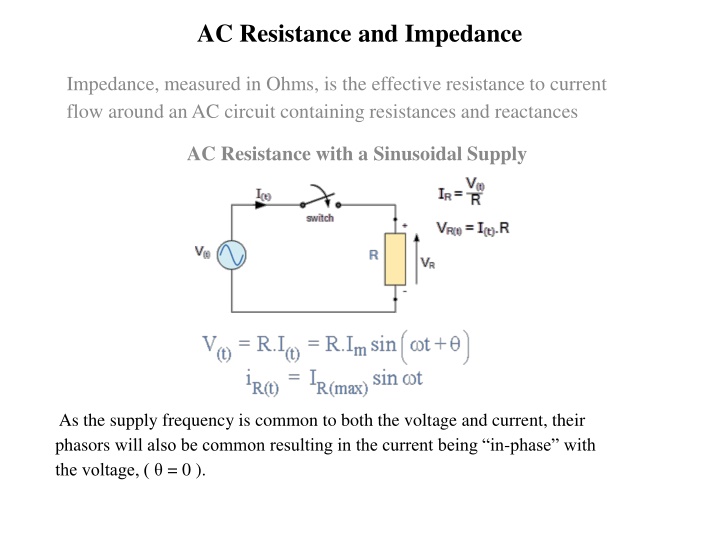
AC Resistance and Impedance Impedance, measured in Ohms, is the effective resistance to current flow around an AC circuit containing resistances and reactances AC Resistance with a Sinusoidal Supply As the supply frequency is common to both the voltage and current, their phasors will also be common resulting in the current being in-phase with the voltage, ( = 0 ).
Sinusoidal Waveforms for AC Resistance This in-phase effect can also be represented by a phasor diagram. In the complex domain, resistance is a real number only meaning that there is no j or imaginary component. Therefore, as the voltage and current are both in- phase with each other, there will be no phase difference ( = 0 ) between them, so the vectors of each quantity are drawn super-imposed upon one another along the same reference axis. The transformation from the sinusoidal time-domain into the phasor-domain is given as.
Phasor Diagram for AC Resistance RMS Relationship Phase Relationship
AC Impedance AC Resistance Example No1 An electrical heating element which has an AC resistance of 60 Ohms is connected across a 240VAC single phase supply. Calculate the current drawn from the supply and the power consumed by the heating element. Also draw the corresponding phasor diagram showing the phase relationship between the current and voltage. 3. As there is no phase difference in a resistive component, ( = 0 ), the corresponding phasor diagram is given as:
AC Resistance Example No2 A sinusoidal voltage supply defined as: V(t) = 100 x cos( t + 30o) is connected to a pure resistance of 50 Ohms. Determine its impedance and the peak value of the current flowing through the circuit. Draw the corresponding phasor diagram. The sinusoidal voltage across the resistance will be the same as for the supply in a purely resistive circuit. Converting this voltage from the time-domain expression into the phasor-domain expression gives us:
AC Inductance and Inductive Reactance The opposition to current flow through an AC Inductor is called Inductive Reactance and which depends lineally on the supply frequency Inductive Reactance Where: XL= Inductive Reactance in Ohms, ( ) (pi) = a numeric constant of 3.142 = Frequency in Hertz, (Hz) L = Inductance in Henries, (H) We can also define inductive reactance in radians, where Omega, equals 2 .
AC Inductance with a Sinusoidal Supply This simple circuit above consists of a pure inductance of L Henries ( H ), connected across a sinusoidal voltage given by the expression: V(t) = Vmaxsin t. When the switch is closed this sinusoidal voltage will cause a current to flow and rise from zero to its maximum value. This rise or change in the current will induce a magnetic field within the coil which in turn will oppose or restrict this change in the current. But before the current has had time to reach its maximum value as it would in a DC circuit, the voltage changes polarity causing the current to change direction. This change in the other direction once again being delayed by the self-induced back emf in the coil, and in a circuit containing a pure inductance only, the current is delayed by 90o.
The applied voltage reaches its maximum positive value a quarter ( 1/4 ) of a cycle earlier than the current reaches its maximum positive value, in other words, a voltage applied to a purely inductive circuit LEADS the current by a quarter of a cycle or 90oas shown below. Sinusoidal Waveforms for AC Inductance
This effect can also be represented by a phasor diagram were in a purely inductive circuit the voltage LEADS the current by 90o. But by using the voltage as our reference, we can also say that the current LAGS the voltage by one quarter of a cycle or 90oas shown in the vector diagram below. Phasor Diagram for AC Inductance So for a pure loss less inductor, VL leads ILby 90o, or we can say that IL lags VLby 90o.
AC through a Series R + L Circuit Series Resistance-Inductance Circuit Vector Diagrams for the Two Pure Components
The RLImpedance Triangle Phase Angle
AC Inductance Example No1 In the following circuit, the supply voltage is defined as: V(t)= 230 sin( 314t 30o ) and L = 2.2H. Determine the value of the current flowing through the coil and draw the resulting phasor diagram. The voltage across the coil will be the same as the supply voltage. Converting this time domain value into polar form gives us: VL= 230 -30o(v). The inductive reactance of the coil is: XL= L = 314 x 2.2 = 690 . Then the current flowing through the coil can be found using Ohms law as: With the current lagging the voltage by 90othe phasor diagram will be.
AC Inductance Example No2 A coil has a resistance of 30 and an inductance of 0.5H. If the current flowing through the coil is 4amps. What will be the value of the supply voltage if its frequency is 50Hz.
Then the voltage drops across each component is calculated as: The phase angle between the current and supply voltage is calculated as:


