Acceleration Analysis of Slider Crank Mechanism and Truss Problems
Explore acceleration analysis of a slider crank mechanism and truss problems, focusing on support identification, reaction forces, and equilibrium conditions. Study the magnitude and direction of accelerations at specific points, along with the types of support and forces acting on truss members. Dive into the graphical illustrations and step-by-step analysis to enhance your understanding of engineering principles.
Download Presentation

Please find below an Image/Link to download the presentation.
The content on the website is provided AS IS for your information and personal use only. It may not be sold, licensed, or shared on other websites without obtaining consent from the author. If you encounter any issues during the download, it is possible that the publisher has removed the file from their server.
You are allowed to download the files provided on this website for personal or commercial use, subject to the condition that they are used lawfully. All files are the property of their respective owners.
The content on the website is provided AS IS for your information and personal use only. It may not be sold, licensed, or shared on other websites without obtaining consent from the author.
E N D
Presentation Transcript
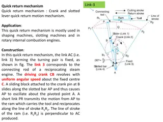
Acceleration analysis Acceleration analysis of slider crank mechanism AB2 AB Link OA rotates with constant speed. aA aB/A AB Acceleration of point A. Magnitude: aA = OA2 OA Acceleration of point B. Direction: Horizontal Direction: Along AO
Acceleration analysis Acceleration analysis of slider crank mechanism AB2 AB Link OA rotates with constant speed. aA aB/A AB aA Acceleration of point A. Magnitude: aA = OA2 OA Acceleration of point B. Direction: Horizontal Direction: Along AO
Acceleration analysis Acceleration analysis of slider crank mechanism AB2 AB Link OA rotates with constant speed. aA aB/A AB aA Acceleration of point A. Magnitude: aA = OA2 OA = 2 m/s Acceleration of point B. Direction: Horizontal Direction: Along AO Define scale: b OA2 OA = 2.5 cm ( o, g) AB a OA2 OA AB2 AB
Truss problem Step-1 o Identify the types of support in truss member
Ladder problem Step-1 o Identify the types of support in truss member 12 k N 20 k N 2 m 2 m 3 m 2 m A B C D E H Roller support 4 m G F Fixed support
Truss problem Step-2 o Apply support reaction force in truss member
Truss problem 1. Roller support: Free body diagram of entire truss member. Only reaction force occur perpendicular surface. 12 k N 20 k N to contact 2 m 2 m 3 m 2 m A B C D E 2. Fixed support : 12 k N 20 k N Reaction horizontal direction both. force occur in RAY H and vertical 4 m G Step-3 RFx o Apply force and moment equilibrium conditions a) Fx = 0 b) Fy = 0 c) MP = 0 P is a point about which moment need to calculated. (You have to choose point P) F RFY
Truss problem 1) Force equilibrium about x- axis. Free body diagram of entire truss member. 12 k N 20 k N Fx = 0 2 m 2 m 3 m 2 m A B C D RFx = 0 E 2) Force equilibrium about y axis. RAY H 4 m Fy = 0 G Line of action of force 20 kN RAY + RFY = 32 KN. 3) Moment equilibrium about Line of action of force RAY X F Y RFx Perpendicular from F on line of action of force RAY distance point F. RFY Perpendicular from F on line of action of force 20 KN act at point E. distance RAY * FX ( ACW) + 20 kN * 3 m (ACW)= 0 RAY * 6 m + 20 KN * 3 m = 0 RAY = - 10 KN
Truss problem RAY + RFY = 32 KN. - 10 KN + RFY = 32 KN. RFY = 42 KN.
Truss problem 12 k N 20 k N 1 a) Determine the forces in members. all the 2 m 2 m 3 m 2 m A B C D E -10 KN H 1. Calculate angle ( ) 4 m In ADF, p b G = tan ( ) tan ( ) = 4 F 6 = 33.690 42 KN 2. Calculate angle ( ) In DEF, p b tan ( ) = tan ( ) = 4 = 53.130 3
Truss problem 1 a) Calculate member force in all member. Method of Joint 1. First we select a joint where only two connected. 12 k N 20 k N 2 m 2 m 3 m FED 2 m member is A B C D E -10 KN o Joint A ( AB and AH ) H o Joint E ( ED and EF) FEF 2. Draw Free body diagram of 4 m G joint at E or A (it is upto you which joint you F wanted to draw first) Y I will select Joint E. 42 KN 20 k N FBD of Joint E Force equilibrium about x- axis - FED FEF Cos( ) = 0 Force equilibrium about y-axis - 20 FEF Sin ( ) = 0 Solve this two equation find the force FED and FEF E FED X FEF
Truss problem 1 a) Calculate member force in all member. Method of Joint 12 k N 20 k N FAB FBC A 3. Select joint A. Draw Free B C D FED E body diagram of joint at A Y FBH FAH -10 KN H FAB X A FEF 4 m G FAB FBC FBH FAH = -10 KN = Sin(90) Sin(90) Sin(180) o Force equilibrium about x- axis F FAB + FAH Cos( ) = 0 42 KN o Force equilibrium about y-axis - 10 - FAHSin ( ) = 0 Solve this two equation find the force FAH and FAB
Truss problem 1 a) Calculate member force in all member. 12 k N 20 k N FAB FBC A B C D FED E FAH -10 KN H FEF FCG 4 m G FCH FAH FCG = = Sin(180) F Sin(180 - ) Sin( ) 42 KN
Truss problem Method of Joint 12 k N 20 k N 4. Now select joint where only FAB FAB FBC two unknown member force. A B C D FED o Joint B ( FBC & FBH) E FBH FAH o Joint F ( FEG & FFD) -10 KN Draw FBD at Joint B H FBC FAB FEF B 4 m FFD G FBH FFG FEF o Force equilibrium about x- axis F FBC - FAB = 0 o Force equilibrium about y-axis 42 KN FBH = 0 FAB is unknown to us So we can find FBC .
Truss problem Method of Joint ABH & BCH are congruent. Therefore angle C = angle A 12 k N 20 k N 4 b) Joint F ( FEG & FFD) FAB FAB FBC Draw FBD at Joint F A FFD B C D FED E FEF FFG FCH = ?? FBH FAH FAH -10 KN FHG = ?? H FEF 4 m FFD G 42 KN FFG Draw FBD at Joint H FEF F FCH = ?? 42 KN FAH FHG = ?? H

