Advanced Concepts in Computer Architecture
Explore advanced concepts in computer architecture, including the design and operation of a 4-bit Adder-Subtractor circuit, a Combinational Circuit Incrementer, and an Arithmetic Circuit. Learn how these circuits perform addition, subtraction, incrementation, and more using logical operations and microoperations.

Download Presentation

Please find below an Image/Link to download the presentation.
The content on the website is provided AS IS for your information and personal use only. It may not be sold, licensed, or shared on other websites without obtaining consent from the author. If you encounter any issues during the download, it is possible that the publisher has removed the file from their server.
You are allowed to download the files provided on this website for personal or commercial use, subject to the condition that they are used lawfully. All files are the property of their respective owners.
The content on the website is provided AS IS for your information and personal use only. It may not be sold, licensed, or shared on other websites without obtaining consent from the author.
E N D
Presentation Transcript
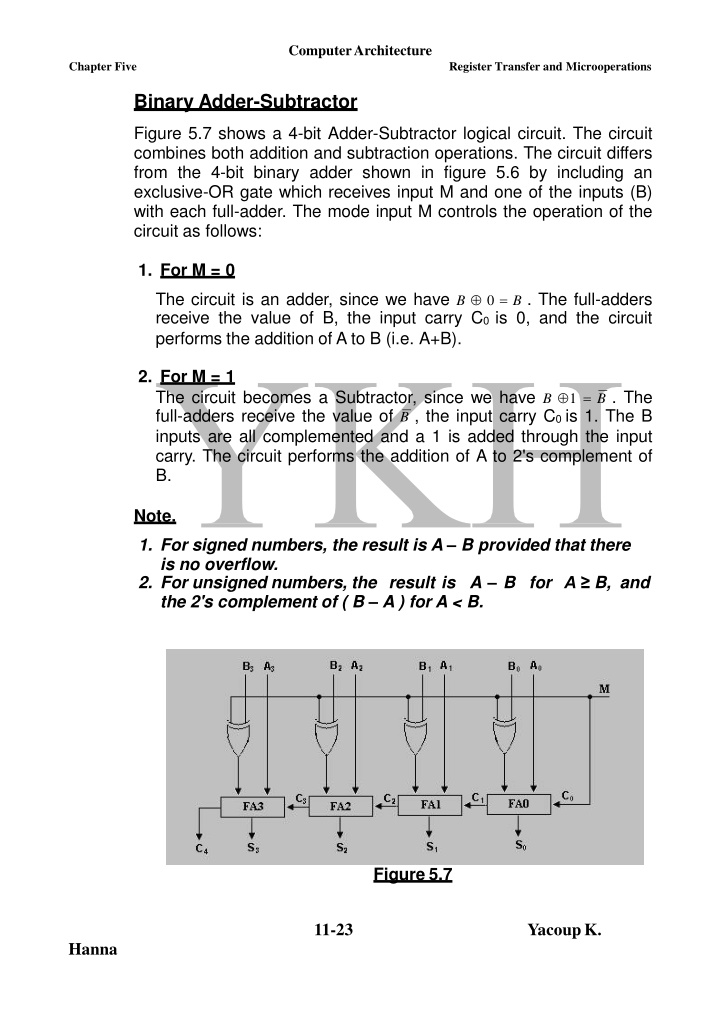
ComputerArchitecture Chapter Five Register Transfer and Microoperations Binary Adder-Subtractor Figure 5.7 shows a 4-bit Adder-Subtractor logical circuit. The circuit combines both addition and subtraction operations. The circuit differs from the 4-bit binary adder shown in figure 5.6 by including an exclusive-OR gate which receives input M and one of the inputs (B) with each full-adder. The mode input M controls the operation of the circuit as follows: 1. For M = 0 The circuit is an adder, since we have B 0 = B . The full-adders receive the value of B, the input carry C0 is 0, and the circuit performs the addition of A to B (i.e. A+B). 2. For M = 1 The circuit becomes a Subtractor, since we have B 1 = B . The full-adders receive the value of B , the input carry C0 is 1. The B inputs are all complemented and a 1 is added through the input carry. The circuit performs the addition of A to 2's complement of B. Note. 1. For signed numbers, the result is A B provided that there is no overflow. 2. For unsigned numbers, the result is A B for A B, and the 2's complement of ( B A ) for A < B. Figure 5.7 11-23 YacoupK. Hanna
ComputerArchitecture Chapter Five Register Transfer and Microoperations Binary Incremental Figure 5.8 shows a 4-bit Combinational Circuit Incrementer. Simply this logic circuit is implemented by means of half-adders connected in cascade. One of the inputs to the least significant half-adder is connected to logic 1 and the other input connected to the least significant bit of the number to be incremented. The circuit receives the four bits A0 to A3, adds 1 to it, and generates the incremented output in S0 to S3. The output carry C4 will be 1 only after incrementing binary number 1111. This also causes output S0to S3 to go to 0 (i.e. 0000). The circuit shown in figure 5.8 can be extended to an n-bit binary Incrementer by extending the diagram to include n half-adders. Keep in mind that the least significant bit must have one input connected to logic 1. Figure 5.8 Arithmetic Circuit Figure 5.9 shows a 4-bit arithmetic circuit. The circuit has four full- adders and four multiplexers for choosing different operations. There are two 4-bit inputs A and B and a 4-bit output D. the 4 inputs from A connected directly to the X inputs of the binary adder, while the other 4 inputs from B and their complements are connected to two of the data inputs of the multiplexers. The remaining two inputs of the multiplexers are connected to logic 0 and logic 1. The two selection inputs, S1 & S0 controls the operation of the four multiplexers. The input carry Cinis connected to the input of the full- adder FA0, while the other carries are connected from one stage to the next. The output of the binary adder s is calculated from the following arithmetic sum: D = A + Y + Cin (5.1) 12-23 YacoupK. Hanna
ComputerArchitecture Chapter Five Register Transfer and Microoperations Depending on the two selection inputs S1& S0and by controlling the value of Y and Cin, it is possible to generate the arithmetic microoperations shown in table 5.5. Table 5.5 Select S1 S0 Cin 0 0 0 0 0 1 Input Y Output Type of microoperation D = A + Y +Cin Add without Carry Add with Carry Subtract with Borrow (i.e. D = A B 1) Subtraction of B from A (i.e. A plus 2's Complement of B) Transfer from input A to output D Increment A by 1 Decrement A by 1 Transfer from input A to output D D = A + B D = A + B +1 B B 0 1 0 D = A + B B 0 1 1 1 0 0 1 0 1 1 1 0 1 1 1 D = A + B +1 B 0 0 1 1 D = A D = A +1 D = A 1 D = A Figure 5.9 13-23 YacoupK. Hanna
ComputerArchitecture Chapter Five Register Transfer and Microoperations 5.5. Logic Microoperations Logic microoperations specify binary operations for string of bits stored in registers. These operations consider each bit of the register separately and treat them as binary variables. Examples of these microoperations are the following: R1 R1 R2 P : (1) This microoperation performs the exclusive-OR between the individual bits of registers R1 & R2 provided that the control variable P = 1, and store the result in register R1. As a numerical example, let the contents of R1 = 1001 and R2 = 1101, then 1001 Content of R1 1101 0100 Content of R2 Content of R1 after P = 1 P +Q : R1 R2 + R3, R4 R5 R6 (2) This microoperation performs the OR function between the individual bits of registers R5 & R6, store the result in R4, and adding the contents of registers R2 and R3 , store the result in R1 provided that the control variables P OR Q = 1. In the above statement the + between P & Q is an OR operation, while the + between R2 and R3 specifies an add microoperation. The symbol between registers R5 & R6 stands for the OR microoperation. 14-23 YacoupK. Hanna
ComputerArchitecture Chapter Five Register Transfer and Microoperations Hardware Implementation of Logic Microoperations Generally, there are 16 logic microoperations, but most computers use only four, which are AND, OR, XOR, and Complement from which all others can be derived. Figure 5.10 shows one stage of a circuit that generates the four basic logic microoperations. The circuit consists of four logical gates AND, OR, XOR, and NOT gates and one Multiplexer. The outputs of the four gates are applied to the data inputs of the multiplexer. The data inputs of the multiplexer are chosen according to the two selection inputs S1& S0as shown in table5.6. Note that the diagram shows one typical stage with subscript i. For a logic circuit with n bits, the diagram must be repeated n times for i = 0, 1, 2, , n-1. The selection inputs S1& S0are applied to allstages. 5.6. Shift Microoperations Shift microoperations are used for serial transfer of data. Also these microoperations are used in conjunction with other operations such as arithmetic, logic, and other data processing operations. The contents of a register can be shifted to the right or to the left. At the same time that the bits are shifted, the first flip-flop receives the binary information from the serial input. During a shift left operation, the serial input transfers a bit into the rightmost position, while during a shift right operation, the serial input transfers a bit into the leftmost position. The information transferred through the serial input determines the type of shift. 15-23 YacoupK. Hanna
ComputerArchitecture ChapterFive Register Transfer and Microoperations There are three types of shifts: - 1. Logical Shift. A logical shift transfers 0 through the serial input. The symbol shl stands for logical shift-left, while shr stands for logical shift-right. Examples R shl R (1) This microoperation, shift to the left one bit the contents of register R. The bit transferred to the end position through the serial input is assumed to be 0. R shr R (2) This microoperation, shift to the right one bit the contents of register R. The bit transferred to the end position through the serial input is assumed to be 0. 2. Circular Shift. The circular shift circulates the bits of the register around the two ends without loss of information. This connecting the serial output of the shift register to its serial input. The symbol cil stands for circular shift-left, while cir stands for circular shift-right. is accomplished by Examples (1) R cil R This microoperation circulates to the left one bit the contents of register R. No bit transferred to any end positions of the specified register. (2) R cir R This microoperation circulates to the right one bit the contents of register R. No bit transferred to any end positions of the specified register. 16-23 YacoupK. Hanna
ComputerArchitecture Chapter Five Register Transfer and Microoperations 3. Arithmetic Shift. Arithmetic Shift Microoperations shift a signed binary number to the left (multiplies the signed binary number by 2) or to the right (divides the signed binary number by 2). Arithmetic shifts must leave the sign bit unchanged because the sign of the number remains the same when the number is multiplied or divide by 2. For signed binary numbers, the left bit in a register holds the sign bit (0 for positive and 1 for negative), and the remaining bits hold the number magnitude. Negative complement form. Figure 5.11 shows a typical register of n bits, where bit Rn-1 in the leftmost position holds the sign bit, and Rn-2 is the most significant bit of the number with R0the least significant bit. numbers are in 2's Figure 5.11 There are two types of Arithmetic shift microoperations: - 1. Arithmetic Shift-Right Microoperation. The Arithmetic Shift-Right Microoperation leaves the sign bit unchanged with shifting the number (including the sign bit) to the right. Here, Rn-1remains the same; Rn-2receives the bit from Rn-1, and so on for the other bits in the register. The bit in R0is lost. 2. Arithmetic Shift-Left Microoperation. The Arithmetic Shift-Left Microoperation inserts a 0 into R0, and shifts all other bits to the left. Here, the initial bit of Rn-1is lost and replaced by the bit from Rn-2. If the bit in Rn-1 changes in value after the shift, a sign reversal occurs. This happens if the multiplication by two causes an overflow. 17-23 YacoupK. Hanna
ComputerArchitecture Chapter Five Register Transfer and Microoperations Hardware Implementation of Shift Microoperations Figure 5.12 shows the combinational circuit that can performs 4-bit shift operations. The 4-bit shifter has four data inputs, A0, A1, A2, and A3, with four data outputs, H0, H1, H2, and H3. There are two serial inputs, one for shift left (IL) and the other for shift right (IR). When the selection input S = 0, the input data are shifted right (down in the diagram), while when S = 1, the input data are shifted left (up in the diagram). Table 5.7 is a function table that shows how the data shifts after the shift operation. Figure 5.12 Table 5.7 Output H0 H1 H2H3 IR A0 A1 A2 A1 A2 A3 IL Select Input S 0 1 18-23 YacoupK. Hanna
ComputerArchitecture Chapter Five Register Transfer and Microoperations 5.7 Arithmetic Logic Shift Unit In previous sections, we studied individually the circuits that perform the arithmetic, logic, and Shift microoperations. In computer system, this is not the case, in which a number of storage registers connected to a common operational unit called an Arithmetic Logic Unit (ALU) employs these microoperations. To perform a microoperation, the contents of specified registers are placed in the inputs of the common ALU. The ALU performs an operation and the result of the operation is then transferred to a destination register. The shift microoperations are often performed in a separate unit, but sometimes the shift unit is made part of the overall ALU. Figure 5.13 shows a one stage of an arithmetic logic shift unit. Where: - i: is a subscript designates a typical stage. Ai and Bi : The two Inputs applied to both the arithmetic and logic units. S0 to S1: are the selection inputs, which select a particular microoperation. S2 to S3: are the selection inputs, which select between Ei, Hi, Ai-1 (the shift right operation), and Ai+1 (the shift left operation). Ci: is the input carry of the stage i. Ci+1: is the output carry of the stage i. Ei: is the output of the arithmetic circuit. Hi: is the output of the logic circuit. Fi: is the output of the stage i For an n-bit ALU, the circuit of figure 5.13 must be repeated n times. The output carry Ci+1 of a given arithmetic stage must be connected to the input carry Ciof the next stage in sequence. The input carry to the first stage is the input carry Cin, which provides a selection variable for the arithmetic operations. The circuit shown in the figure provides eight arithmetic operation, four logic operations, and two shift operations. The operations are selected according to the variables S3, S2, S1, S0, and Cin. The input carry Cin used for selecting arithmetic operations only. 19-23 YacoupK. Hanna
ComputerArchitecture Chapter Five Register Transfer and Microoperations Table 5.8 lists the fourteen operations of the ALU. When S3S2= 00, the first eight arithmetic operations are selected. For S3S2 = 01, the next four logic operations are selected. The input carry has no effect during the logic operations and is marked with don't-care x's. The last two operations are shift operations and are selected with S3S2= 10 and 11. The other three selection inputs have no effect on the shift. Figure 5.13 20-23 YacoupK. Hanna
ComputerArchitecture ChapterFive Register Transfer and Microoperations Table 5.8 Operation elect S3 S2 S1 S0 Cin 0 0 0 0 0 0 0 0 0 0 0 0 0 0 0 0 0 1 0 1 0 1 0 1 1 0 1 1 Operation Function 0 0 0 0 1 1 1 1 0 0 1 1 x x 0 0 1 1 0 0 1 1 0 1 0 1 x x 0 1 0 1 0 1 0 1 x x x x x x Transfer A Increment A Addition Add with carry Subtract with borrow F =A F = A + 1 F = A +B F = A + B +1 F = A +B F = A + B + 1 Subtraction F = A 1 F =A F = A B F = A B F = A B F =A F = shr A F = shl A Decrement A Transfer A AND OR XOR Complement A Shift right A into F Shift left A into F 21-23 YacoupK. Hanna