Advanced Inter-user Interference Modeling for Cellular Networks
Explore the detailed evaluation of inter-user interference in cellular networks, focusing on modeling for phase I scenarios with varied antenna configurations, correlation considerations, and codebook types. The analysis covers PMI selection and precoding matrix generation options for target and interference users.

Download Presentation

Please find below an Image/Link to download the presentation.
The content on the website is provided AS IS for your information and personal use only. It may not be sold, licensed, or shared on other websites without obtaining consent from the author. If you encounter any issues during the download, it is possible that the publisher has removed the file from their server.
You are allowed to download the files provided on this website for personal or commercial use, subject to the condition that they are used lawfully. All files are the property of their respective owners.
The content on the website is provided AS IS for your information and personal use only. It may not be sold, licensed, or shared on other websites without obtaining consent from the author.
E N D
Presentation Transcript
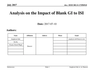
3GPP TSG-RAN4 Meeting #98-bis-e Electronic Meeting, 12th 20thApr. 2021 Agenda item: 8.14.2 R4-21xxxxx Approval Document for: Way Forward on MMSE-IRC for intra-cell inter-user interference Huawei, HiSilicon
Inter-user interference modeling for phase I evaluation
Inter-user interference modeling for phase I evaluation Paired UE number Under 2Tx and 4Tx with random PMI for target UE, use 1 target UE + 1 interference UE as starting point for initial simulation For scenario of Tx more than 4, other options not precluded Interested companies can bring analysis on scenarios of interference UE more than 1 Rank for target and interference PDSCH Option 1: Rank 1 only for target UE and interference UE Option 2: Cover both rank 1 and rank 2 per UE Option 2A: [1+1], [2+2] for target UE and interference UE Option 2B: [1+1], [2+1] for target UE and interference UE Option 2C: [1+1], [1+2] for target UE and interference UE
Inter-user interference modeling for phase I evaluation Correlation between the propagation channel of the paired UEs Ensure Low correlation between the co-scheduled UEs Antenna configuration For Rx antenna number Cover both 2Rx and 4Rx For Tx antenna number Using 2Tx and 4Tx with random PMI for target UE as starting point for initial simulation Other options not excluded Interested companies can bring analysis with 8Tx and 16Tx cases with following PMI for target UE
Inter-user interference modeling for phase I evaluation Codebook Type Option 1: Use Type I Single Panel with random PMI for initial evaluation Other options are not precluded
Inter-user interference modeling for phase I evaluation PMI selection and precoding matrix generation Option 1: Random based target UE PMI selection Option 1A: Random selection based precoder generation with QRD orthogonalization processing as below Option 1B: Random PMI selection for the target UE, and select the precoder for the interference UE to ensure orthogonality Option 1C: Random PMI selection for both target and interference UE, with ensuring the selected PMI matrix shall not be identical to the precoding matrix applied for the UE under test Option 2: Feedback-based target UE PMI selection Option 2A: If the feasibility can be confirmed by the TE vendor, use ZF precoding based on the reported PMI from the target UE, and the randomly generated PMI from the interference UE(s) Option 2B: Feedback-based PMI selection for the target UE, select the precoder for the interference UE to ensure the orthogonality Option 2C: Feedback-based PMI selection for target UE, and random PMI selection for interference UE, with ensuring the selected PMI matrix shall not be identical to the precoding matrix applied for the UE under test Option 3: Fixed precoding matrix for one or both co-scheduled UEs TE vendors feedback on the feasibility of the above options: Keysight: 1A and 2A are of less feasibility. The preferences are in this order 3, 1C, 1B, 2B. R&S: 1A and 2A is very complex and not really feasible. Preference in order 3 > 1C >> 1B. Anritsu: Need more time to study.
Inter-user interference modeling for phase I evaluation PRB bundling size and precoding granularity For 2Tx and 4Tx Option 1: Per 2 PRBs for frequency domain and per slot for time domain Option 2: Per 4 PRBs for frequency domain and per slot for time domain For more than 4Tx(if introduced): Option 1: Wideband for 8Tx for target and paired UEs. For 16Tx, use subband precoding if it is feasible for TE to calculate ZF precoding matrix per subband Other option not precluded MCS for interfering PDSCH Random 16 QAM signal generation
Inter-user interference modeling for phase I evaluation DMRS ports for 1 target and 1 interfering UE scenario Option 1: only consider rank 1 transmission Option 1A: DMRS port 0 for target UE, DMRS port 1 for the interference UE, i.e., same CDM group Option 1B: DMRS port 0 for target UE, DMRS port 2 for the interference UE, i.e., different CDM groups Option 2: consider both rank 1 and rank 2 transmission With [2,2] transmission for target UE and interference UE DMRS port 0/1 for target UE, DMRS port 2/3 for the interference UE With rank [1,2] or rank [2,1] transmission for the target UE and interference UE Option 2A: DMRS port 0 (and 1) for target UE, port 2 (and 3) for the interference UE, i.e., use different CDM groups for the target and interference UEs Option 2B: For rank [1,2], DMRS port 0 for target UE, DMRS port 1 and 2 for the interference UE For rank [2,1], DMRS port 0 and 1 for target UE, DMRS port 2 for the interference UE
Inter-user interference modeling for phase I evaluation DMRS ports for 1 target and more than 1 interfering UE scenario (if introduced) (Further apply the agreement of rank) For rank 1 transmission, Option 1: DMRS port 0 for target UE, DMRS port i for the i-th interference UE (i = 1, 2,...) (China Telecom, Intel) For rank 2 transmission, with same rank number per UE, Option 1: DMRS port 0/1 for target UE, DMRS port 2i and 2i+1 for the i-th interference UE e.g. use different CDM group for the target and interference UEs (CTC)
Inter-user interference modeling for phase I evaluation DMRS type and DMRS additional position DMRS Type 1 with 1 additional DMRS Ratio of PDSCH EPRE to DM-RS EPRE 0 dB and -3 dB when the number of DM-RS CDM groups without data is 1 and 2 respectively Whether to use same DMRS pattern and the same sequence for all co-scheduled UEs Option 1: Use the same following DMRS configuration for all co- scheduled UEs Same DMRS type Same DMRS additional position Same scrambling ID Same cell ID Option 2: Different scrambling id for different CDM groups Option 3: No restriction for simulation
Reference receiver for phase I evaluation
Reference receiver for phase I evaluation Candidate Receiver Prioritize MMSE-IRC processing with serving signal demodulation for initial simulation 1? ????? ?+ ??+? ??= ?? Other options are not precluded Option 1: MMSE-IRC processing with joint (serving + interference) signal demodulation 1?, where ??+?= ?? ? ? ??+?= ??+? ?? ??+???+? + ?? Interference estimation for cases with 2 DMRS CDM group Option 1: For cases with 2 DMRS CDM groups, the interference should be estimated based on the REs occupied by both of the two DMRS CDM groups Option 2: Not to consider this scenario Option 3: Up to UE implementation and cannot be specified as simulation assumption
Reference receiver for phase I evaluation Interference estimation granularity Option 1: Per PRB and per slot based interference covariance matrix estimation Option 2: Same with the PRB bundling size Option 3: Up to UE implementation Whether to introduce network assistance to assist the receiver FFS on whether to introduce network assistance and if so how to assist the receiver
PDSCH parameters for phase I evaluation
PDSCH parameters for phase I evaluation SCS 15kHz SCS for FDD 30kHz SCS for TDD Channel bandwidth Option 1 For FDD 15kHz SCS: Cover 10MHz and 50MHz CBW For TDD 30kHz SCS: Cover 40MHz and 100MHz CBW Option 2: For FDD 15kHz SCS: Cover 10MHz For TDD 30kHz SCS: Cover 40MHz Option 3: For FDD 15kHz SCS: Cover 10MHz and 40MHz CBW For TDD 30kHz SCS: Cover 40MHz and 100MHz CBW TDD configuration 7D1S2U(6D+4G+4U) for 30kHz TDD
PDSCH parameters for phase I evaluation MIMO correlation for each UE Cover XP High, XP Medium and XP low for phase I evaluation, and make further down-selection based on results Propagation condition Cover both TDLA30-10 and TDLC300-100 in phase I, and decide whether down-selection or adjustment is needed based on the simulation results MCS for target UE Cover QPSK MCS 4, 16QAM MCS 13, and 64QAM MCS 19 for initial simulation Rank 1: QPSK, 16QAM Rank 2: 16QAM, 64QAM Other options are not preclude PDSCH mapping type Type A
PDSCH parameters for phase I evaluation PDSCH Resource Allocation Time Domain Starting symbol 2 and duration 12 as baseline Frequency Domain Full PRB allocation as baseline HARQ Process Number 4 for FDD 15kHz SCS and 8 for TDD 30kHz SCSMCS for target UE SSB configuration SSB position in burst: first SSB in Slot#0; SSB periodicity: 20ms. The slot #0 in every 20 ms is not scheduled for PDSCH transmission
PDSCH parameters for phase I evaluation TRS, NZP CSI-RS and ZP CSI-RS Configuration For TRS and ZP CSI-RS, reuse the Rel-15 assumptions for PDSCH demodulation requirement. For NZP CSI-RS, Reuse the Rel-15 general assumptions for PDSCH demodulation requirement and extend the configuration for more than 4 ports The configuration should be extended if 8Tx or 16Tx is used Performance evaluation metrics Measure the 70% max throughput performance of the target UE Evaluate the gain of MMSE-IRC over MMSE under the same simulation setup as baseline Interested companies also encouraged to bring analysis for performance difference between the case with and without co- scheduled UE