"Explore the comprehensive capabilities of a program enabling precise measurements at specific positions within sample assemblies, offering valuable insights through diffraction, imaging, scanning, ultrasonics, and more. Follow step-by-step instructions for a successful initialization and data collection process."
Please find below an Image/Link to download the presentation.
The content on the website is provided AS IS for your information and personal use only. It may not be sold, licensed, or shared on other websites without obtaining consent from the author. If you encounter any issues during the download, it is possible that the publisher has removed the file from their server.
You are allowed to download the files provided on this website for personal or commercial use, subject to the condition that they are used lawfully. All files are the property of their respective owners.
The content on the website is provided AS IS for your information and personal use only. It may not be sold, licensed, or shared on other websites without obtaining consent from the author.
E N D
Presentation Transcript
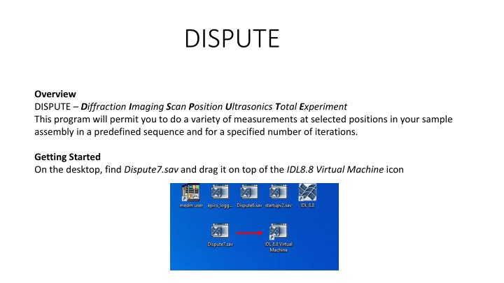
DISPUTE Overview DISPUTE Diffraction Imaging Scan Position Ultrasonics Total Experiment This program will permit you to do a variety of measurements at selected positions in your sample assembly in a predefined sequence and for a specified number of iterations. Getting Started On the desktop, find Dispute7.sav and drag it on top of the IDL8.8 Virtual Machine icon
When the IDL Virtual Machine opens Click Click to Continue Wait for Dispute7 to start and get Initialized. Be patient! This may take a few minutes. You will then see the following window.
Do not proceed until you see the message: Initialization complete. Ready You may see some error messages if some of the equipment has not be turned on or is malfunctioning. If no ultrasonic measurements are planned you may see: There is a problem with the Ztec scope START Start the data collection process Always do a Check Input before starting. STOP Stop the data collection at the end of a cycle. ABORT Stop the data collection abruptly. Note: Fields with a white background can be edited, fields with a grey background cannot be edited except for dropdown menus.
Operational Information Fields General Status Errors and Warnings Name for the Next diffraction pattern Name of the Last Image file collected Name of the Next ultrasonic wave file The name fields can not be changed with DISPUTE. See the next slide for changing file names. The Status and Error fields can be cleared with the Tools menu.
Changing Filenames 1. Diffraction filename. Edit the file Lastfilewritten.txt located on the T: drive and change the name. T:\Silica\Quartz\SiO2_71\SIO2_71_0000.med T:\test\kentest\test1\kjb01_0001.med Click on Check Input. The next file will be kjb01_0002.med 2. Image Filename. Change the name of the file in the appropriate MEDM window and click Check Input. 3. U-Filename. Edit the file Lastwavefilewritten.txt located on the T: drive and change the name. Click Check Input.
Data Collection Parameters 1. 2. 3. 4. 5. 6. 7. Preset Time 1. Count time in seconds for procedure Diffraction Preset Time 2. Count time in seconds for procedure Diffraction 2 Slit X Opened. Position defined as Slit X opened Slit X Closed. Position defined as Slit X closed. Does not have to be 0.0 Slit Y Opened. Position defined as Slit Y opened Slit X Closed. Position defined as Slit Y closed. Does not have to be 0.0 Three S-wave and P-wave Frequencies, Acquisition counts and wait times can be defined. AcqCount1/2/3. Number of Udata waveforms to acquire and process. Default is Average. Wait1/2/3. Time to wait(sec) after initiating a Udata acquisition. Default values are associated with Acqcount1/2/3 but can be manually edited. 10. Two sets of U-bits can be set. Ubits define 6 bits labeled 0 to 5 to form a binary number. Examples: Value of 3 sets bits 0 and 1, value of 12 sets bits 2 and 3 11. Flag 1 is used when doing diffraction and Udata. Flag1=0, let diffraction finish after Udata finished. Flag1=1, terminate diffraction when Udata is completed. 12. Delay time. Time in seconds for procedure Delay. 13. The Additional Step Scanning Parameters work in conjunction with X Range and Y Range for use with the three Step Scan procedures. Ubit Freq Acqcount Wait 0 S1 1 1 1 P1 1 1 8. 2 S2 2 1 9. 3 P2 2 2 4 S3 3 2 5 P3 3 2
Main Measurement Selections A sequence of up to 14 positions can be selected to perform 1 of 16 measurements. The sequence terminates at the first End measurement. The sequence repeats Cyc Req times. X Range and Y Range are used in scanning measurements. Starting Positions Choice of measurements Drop Down List 14 Press X and Y positions where the specified measurements will be made. Preloaded with starting X and Y. 0 Use Main Folder 1 Sub Folder A 2 Sub Folder B . . 6 Sub Folder F
Example 1: Cell assembly with Sample and Standard Step 1. Diffraction of sample at Y=4.0, count time 10 seconds. Data saved in main folder. T:\test\kentest\test1 Step 2. Imaging at Y=4. Image saved main folder. T:\test\kentest\test1 Step 3. Diffraction of standard at Y=5.0 Data saved in main folder. T:\test\kentest\test1 This sequence is repeated 5 times. Cyc Req is 5
Example 2: Cell assembly with Sample, Standard and 2 foil markers Step 1. Diffraction of sample at Y=4.0, count time 10 seconds. Data saved in subfolder A. T:\test\kentest\test1\A Step 2. Imaging at Y=3. Image saved in main folder. T:\test\kentest\test1 Step 3. Imaging at Y=5. Image saved in main folder T:\test\kentest\test1 Step 4. Diffraction of standard at Y=4.5, Data saved in subfolder B. T:\test\kentest\test1\B This sequence is repeated 10 times. Cyc Req is 10
Example 3: Cell assembly with Standard and Sample Step scanning Step 1. Diffraction of standard at Y=4.5 Data saved in subfolder A. T:\test\kentest\test1\A Step 2. Imaging. Data saved in main folder T:\test\kentest\test1 Step 3. 2-d step scan of sample(Y-X) centered at X= 17.7552, Y=0.4 5 points along Y with a width of 0.4. 3 points along X with a width of 0.1. Scan is repeated 2 times. Cycles=2 Data saved in subfolder B. T:\test\kentest\test1\B Sequence is repeated 6 times. Cyc Req = 6