Advanced Memory Technology & Protection
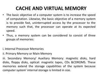
This lecture delves into memory technology advancements, focusing on the internal workings of memory chips, virtual memory systems, and virtual machines to safeguard computer systems. Topics covered include memory organization, performance metrics, SRAM vs. DRAM, DRAM cell structures, access protocols, and more.

Download Presentation

Please find below an Image/Link to download the presentation.
The content on the website is provided AS IS for your information and personal use only. It may not be sold, licensed, or shared on other websites without obtaining consent from the author.If you encounter any issues during the download, it is possible that the publisher has removed the file from their server.
You are allowed to download the files provided on this website for personal or commercial use, subject to the condition that they are used lawfully. All files are the property of their respective owners.
The content on the website is provided AS IS for your information and personal use only. It may not be sold, licensed, or shared on other websites without obtaining consent from the author.
E N D
Presentation Transcript
EE 194: Advanced VLSI Spring 2018 Tufts University Instructor: Joel Grodstein joel.grodstein@tufts.edu Verification 1
What is verification? The design process (highly simplified) Talk to your customer Write the product spec Implement the product Validation Verification Validation checks to see if you are building what the customer wants Verification compares the spec vs. the implementation For us, typically the implementation is RTL code EE 194/Adv. VLSI Joel Grodstein 2
What is RTL? Register-Transfer Level Written at the level of registers, gates. Usually a (e.g.,) 64-bit bus is just one signal; ditto for the registers that store it Does not show individual transistors EE 194/Adv. VLSI Joel Grodstein 3
PC offset adder example address_I1[39:0] adr_I0[39:0] D Q adr_I1[39:0] adder offset_I0[7:0] SO_I1[10:0] SO_I0[10:0] D Q shifter shiftL_I0[1:0] CLK_I1 Function: Add a shifted offset to the PC Uses? Note the pipe-stage naming convention Shift amount can be 0, 1, 2 (not 3) Maybe we don t want to build shift-by-3 hardware There s a validbit too (but it doesn t fit on the slide!) Branches, immediate-field offsets EE 194/Adv. VLSI Joel Grodstein 4
System Verilog adr_I1[39:0] adr_I0[39:0] D Q adr_I1[39:0] adder offset_I0[7:0] SO_I1[10:0] SO_I0[10:0] D Q shifter shiftL_I0[1:0] CLK_I1 module pc_adder (input node[39:0] adr_I0, input node[7:0] offset_I0, input node[1:0] shiftL_I0, output node[39:0] adr_I1); node[39:0] adr_I1; node[10:0] SO_I0, SO_I1; always_ff @(posedge CLK_I1) adr_I1 = adr_I0; SO_I1 = SO_I0; SO_I0 = offset_I0 << shiftL_I0; adr_I1 = adr_I1 + SO_I1; endmodule EE 194/Adv. VLSI Joel Grodstein 5
Why is verification so important? How many of you have ever written a non-trivial computer program? How many of you always have your programs work perfectly the first time? Designing things is easy. Designing things that work is not so easy! We all agree that verifying stuff we design is important. But why build virtual models of it? Why not just build the real thing, try it out and iterate? EE 194/Adv. VLSI Joel Grodstein 6
Pentium FDIV bug Discovered in Dec 1994 by Thomas Nicely professor of math, working with prime numbers in Excel Discovered in May 1994 by an Intel verification coop Estimates of severity: Intel: 1 mistake every 27000 years IBM: 1 mistake every 24 days Byte magazine: 1 in 9 billion floating point divides with random parameters would produce inaccurate results Consequences: December 1994: Intel recalled the processors. January 1995: Intel announces $475M charge against earnings EE 194/Adv. VLSI Joel Grodstein 7
Jobs doing validation Trends in Functional Verification: A 2014 Industry Study by Mentor Graphics Survey of 2000 people in the VLSI chip industry Conclusions: Average of 11 ver. engineers per project, vs. 10 design engineers (and design engineers spend 47% of their time in verification). 3.7% CAGR for design engineers and 12.5% for verification engineers 30% of products ship on first tapeout EE 194/Adv. VLSI Joel Grodstein 8
Who should do verification? Should an RTL designer do their own verification? Pros: They are probably the person who best understands the RTL model. They understand what the chip is supposed to do Cons: What if the RTL architect misunderstands the spec; and thus codes the wrong RTL; and thus writes tests that merely validate that he correctly implemented the wrong thing. Hopefully a separate verification person is unlikely to misunderstand the spec in the same way as the architect RTL architect does not understand verification tooling Typically, the cons are more important. EE 194/Adv. VLSI Joel Grodstein 9
What skills do you need for verification? Verification people must understand hardware, software, and architecture think about how to break things have a jack-of-all-trades mentality (though arguably not that much circuit design). EE 194/Adv. VLSI Joel Grodstein 10
How do you test a CPU RTL? First idea: Write the RTL. Write some more. Eventually you re done. Run the RTL on some assembly code. Does it get the right answer? Will that idea work? How much effort is it to test the RTL? Problems? You have to wait until you re fully done with the RTL before you can test it Consider: 100 people, 20 teams of 5 people each writing code for one unit. Do you want to test the entire 1M lines of code at once, or write unit tests first? Clearly the latter! But now you have a problem: no unit will run assembly code by itself! So what do you do? Sure Not much EE 194/Adv. VLSI Joel Grodstein 11
Unit testing How do you test a single unit? (E.g., the PC offset-adder unit) By itself, it cannot run assembly code at all Its behavior can (in general) be quite hard to specify. This problem is not just CPU-specific; many systems are easier to understand at the top level We now need multiple pieces First, the RTL (e.g., for our offset adder) Second, some way to generate tests. Third, some way to know if our RTL got the right answer. Let s look at those pieces. EE 194/Adv. VLSI Joel Grodstein 12
Ways to generate tests Focused tests A verification engineer hand-writes a specific test Pro: you get a test targeted at the specific feature you want to test Con: takes a long time to write each test What tests might you write for our PC offset adder? Try every shift amount If it s a carry-bypass adder, perhaps try input values that swing all interior muxes both ways But what if the actual bug is something you can t predict? How can you find it without generating lots of tests? Random tests Constrained-random tests EE 194/Adv. VLSI Joel Grodstein 13
Ways to generate tests Focused tests A verification engineer hand-writes a specific test Random tests Get more tests the easy way: generate them randomly Just generate random values for all of the inputs. Easy to generate a ton of tests Any issues? Shift amount=3 is not valid Might pick values that overflows 40 bits What if it s not easy to know the right answer? Constrained-random tests EE 194/Adv. VLSI Joel Grodstein 14
Ways to generate tests Focused tests A verification engineer hand-writes a specific test Random tests Get more tests the easy way: generate them randomly Constrained-random tests Generate tests randomly, but within constraints E.g., constrain shift amount to 0, 1 or 2 (but not 3) Constrain address to be in the range [0,240-(offset<<shift_amount)-1] Any issues now? Or is that the end of the story? Again: how do you know if you got the right answer? How do you know if/when you re done? How do you get it to target parts of the design that you know are quite complex? EE 194/Adv. VLSI Joel Grodstein 15
How do you know if it worked? Hand-design a focused test you (believe you) know the answer What if you have a random or constrained-random test? Reference model: run the test on a golden reference Predictor: much like a reference model (but not always a full model); enough to predict a test outcome Monitor: monitors the test, does coverage checking and sanity checking. EE 194/Adv. VLSI Joel Grodstein 16
Monitors Like assertions in a program Check that error conditions don t occur Are they any better than just waiting for the test to fail and debugging it? Catch error conditions closer to the source for easier debug Often catch bugs even if the test still passes Example: assert property (shiftL_I0 != 3); assert property (clk_I1 -> valid_I0) // roughly EE 194/Adv. VLSI Joel Grodstein 17
What would a reference model look like? adr_I1[39:0] adr_I0[39:0] D Q adr_I1[39:0] adder offset_I0[7:0] SO_I1[10:0] SO_I0[10:0] D Q shifter shiftL_I0[1:0] CLK_I1 module pc_adder (input node[39:0] adr_I0, input node[7:0] offset_I0, input node[1:0] shiftL_I0, output node[39:0] adr_I1); node[39:0] adr_I1; node[10:0] SO_I0, SO_I1; always_ff @(posedge CLK_I1) adr_I1 = adr_I0; SO_I1 = SO_I0; SO_I1 = offset_I0 << shiftL_I0; adr_I1 = adr_I0 + SO_I1; endmodule Would it look any different from the model itself? Why write a reference model that s just the model? EE 194/Adv. VLSI Joel Grodstein 18
What would a reference model look like? adr_I1[39:0] adr_I0[39:0] D Q adr_I1[39:0] adder offset_I0[7:0] SO_I1[10:0] SO_I0[10:0] D Q shifter shiftL_I0[1:0] CLK_I1 If our adder is a carry-bypass adder should we write it as adr_I1 = adr_I1 + SO_I1 ? should we include all of the details of the full adders and bypass muxes? Issues: The lower level we write it at, the more likely it is to be wrong If we write just a + , and the schematics implement a carry-bypass adder, who checks that they re equivalent? Practical answer: write at the highest level that RLS supports often this is still fairly low write a high-level reference model that is likely correct tests compare the two EE 194/Adv. VLSI Joel Grodstein 19
Back to FDiv For a floating-point divide, what might the RTL and the golden reference model look like? Reference model is just a divide (one machine instruction) RTL implements the particular division algorithm we ve chosen (Newton-Raphson, modified Booth, etc) EE 194/Adv. VLSI Joel Grodstein 20
Moving up the hierarchy Go up the hierarchy one level at a time Drop the internal generators Keep the monitors Probably keep the predictors. Industry mostly uses UVM Universal Verification Methodology A set of System Verilog classes and functions to support everything we ve talked about, and more Can also be used with VHDL models EE 194/Adv. VLSI Joel Grodstein 21
Any issues now? Or is that the end of the story? Again: how do you know if you got the right answer? How do you know if/when you re done? How do you get it to target parts of the design that you know are quite complex? EE 194/Adv. VLSI Joel Grodstein 22
Coverage checking Where we are: you write a lot of RTL code you write a lot of tests for it at various levels of the hierarchy How do you know how much/which RTL you did/didn t test? What you think you tested what you actually tested! Code coverage first and simplest metric I.e., how many lines of your RTL ever even got executed? (code in an if/then/else may not be executed) Related metrics Did each signal get set to both 0 and 1? For every state machine, did every state get reached and every arc get traversed? (depends on your compiler recognizing state machines, which usually isn t hard). EE 194/Adv. VLSI Joel Grodstein 23
Code coverage Thoughts on those code coverage metrics? clearly necessary clearly not sufficient! (Executing code testing code) More sophisticated metrics: not only check whether nodes have toggled also check if there s a path from the node being at the wrong value, to that wrong value being captured/reported How do you know when you re done? Coverage checking just tells you what you ve covered not if what you ve covered is enough . Certainly doesn t guarantee that the chip works EE 194/Adv. VLSI Joel Grodstein 24
Feedback 90-10 rule applies as usual 90% of the work is in hitting 10% of the coverage How do we improve that? Common methodology: Start with a few focused tests; see if the unit is alive Add constrained random tests Measure coverage, find gaps Write more focused tests targeted at the gaps Steer your constrained-random tests Steering: Bias your random-number generators So they (hopefully) target the code you re missing Example: you tried to bias your generator to target the bypass muxes. But coverage data tells you that you didn t So you try again Or, do a better job of targeting whatever other issue is indicated EE 194/Adv. VLSI Joel Grodstein 25
How do you know youre done? In general, you re never 100% sure! Other than formal methods (see later) So what do people actually do? Track bugs found Don t stop until the bug rate drops low enough and stays there long enough. And usually that s good enough But remember the statistic about how often we need multiple tapeouts EE 194/Adv. VLSI Joel Grodstein 26
How do you avoid the FDIV bug? FDIV on two 32-bit operands. How long to test them all? 32 bits * 32 bits = 264 combinations, 1019 Assume we test them using silicon, at 1GHz That s 1010 seconds, or 300 years There s no way to exhaustively test an FDIV How do we not have another $500M charge against earnings? Better public acceptance of bugs Not try any new division algorithms Formal techniques EE 194/Adv. VLSI Joel Grodstein 27
Formal verif of arithmetic Definition of a single-bit full adder: sum = a b cin cout = ab | acin | bcin Can we prove that the following implementation works? p = a b g = a & b s = p cin cout = g | pcin Will that type of strategy work for a carry-bypass adder? In fact, yes! (but it s quite a lot of Boolean algebra) Can you do the same thing for FDIV? It s lots harder, but you can Lots of effort has gone into this FDIV gave people religion Can you prove that a CPU executes an instruction set? Not even close EE 194/Adv. VLSI Joel Grodstein 28
s1 = a & b; s2 = a & !b; s3 = !a; unique case ({s1,s2,s3}) 3b'100: out = in1; 3b'010: out = in2; 3b'001: out = in3; endcase System Verilog supports a unique case statement automatically checks that exactly one choice is active during simulation checks during every cycle of every simulation you run Is simulation good enough, in general? No. What if there s some situation that makes all of s1, s2 and s3 high, but we never test that case? EE 194/Adv. VLSI Joel Grodstein 29
Formal property verification s1 = a && b; s2 = a && !b; s3 = !a; unique case ({s1,s2,s3}) 3b'100: out = in1; 3b'010: out = in2; 3b'001: out = in3; endcase Can we do a Boolean proof? Sure. Try it on the board if you want This is called formal property verification From the Mentor paper: 26% of products do it If you have to work through too much logic to do the proof, the tools explode EE 194/Adv. VLSI Joel Grodstein 30
Formal protocol verification Verifying protocols: networks, cache coherence Deadlock, livelock, forward progress These are very hard to check by normal testing methods. Arguably the most successful use of formal verification Mentor paper: 21% of projects do this EE 194/Adv. VLSI Joel Grodstein 31
A few formal checkers TLA, Murphi and Spin: public-domain tools TLA is Leslie Lamport Murphi is David Dill (Stanford) Spin: primarily targeted at software verification, but also for protocols. See www.spinroot.com JasperGold: commercial software from Cadence EE 194/Adv. VLSI Joel Grodstein 32
Emulators RTL simulation may get 50 cycles/second Simulating a test with 1000 assembly instructions is fine Simulating O/S boot is not! What do you do about that? Emulators are one answer Specialized, dedicated (and > $1M!) hardware for simulation Or you can just put your design into multiple FPGAs (much cheaper, but not great if your design is big) Becoming more and more common for big designs EE 194/Adv. VLSI Joel Grodstein 33
Post-silicon verification We ve been discussing pre-silicon verification RTL model vs. customer spec Time to talk about post-silicon version Silicon vs. customer spec Why do we need this? Sometimes silicon RTL More to the point, pre-silicon verification still left bugs Why might we find bugs more easily post-silicon than pre-? Pre-silicon RTL simulator 50 cycles/second. Silicon 2GHz Run the numbers: (Farm of 100 machines)*(50 cycles/sec)*(31M sec/year) = 155*109 cycles (Quad-socket system)*(2GHz)*(20 seconds) 160 * 109. More testing in the first minute post-silicon than entire pre-silicon! EE 194/Adv. VLSI Joel Grodstein 34
The usual questions Where do the tests come from, and how do you know if they pass? first one: can you boot an O/S? Probably a good 1-20 minutes of code, and mostly if it fails then you don t boot. But you might still boot if some of the instructions that you tested don t work; and there s a lotthat it doesn t test Where else do you collect up code? We all have a ton of code lying around but is it self checking? That s the hard part; with a lot of code, you may not easily know if it passed or failed! But you can collect up any self-checking assembly code over the entire history of programming. Or really, any self-checking C++ code that you can compile to assembly EE 194/Adv. VLSI Joel Grodstein 35
Where can we get new tests? Old tests may not be the best for a new microarchitecture. Where do you get new tests? Random code generator (RCG): randomly generate assembly code (actually it s constrained) The usual problem: It s easy to write random code. But how do you know if it worked? Is it even deterministic? (What if you branch on a register or memory that s not set?) A few resolutions: Initialize all of the registers, and all of the memory you plan to use Generate pseudo-random rather than random. Use an assembly-code simulator to check the results for all regs EE 194/Adv. VLSI Joel Grodstein 36
Papers to read Trends in functional verification: a 2016 industry study, DAC 2017 Functional verification of a Multiple-issue, out-of-order, superscalar Alpha processor the DEC Alpha 21264 microprocessor, DAC 1998 How does this compare to what we discussed in class? To what is done today? Efficient and exhaustive floating point verification using sequential equivalence checking, DVcon 2017 How does this compare to what we discussed in class? What do you think about the amount of human time the process took, and about the formal- verification numbers in the Mentor paper? Post-silicon validation of the IBM POWER8 processor, DAC 2014 What new things did they do that we did not discuss in class? Describe their use of accelerators, irritators; describe the final issue in their future challenges Guidelines: Everyone reads the Mentor paper 2 people read each of the other 3 papers EE 194/Adv. VLSI Joel Grodstein 37
First choice: debug breakpoints, find when the wrong answer commits to a register. So now you know roughly when the problem happens. Now what? Debugging tests: restart-replay, scan for debug, debug triggers EE 194/Adv. VLSI Joel Grodstein 38
In-class paper discussion What statistics from the paper are most interesting or surprising to you? Thoughts about, if the trends in the paper continue, what that implies for the future? Why do you think changes in specification are such a big problem? Do you think some of the trends will get worse or better in the future? Do you trust the methodology? Terms: hardware emulation, formal validation EE 194/Adv. VLSI Joel Grodstein 39