Explore groundbreaking research on Mesh APD technology, 4D tracking noise issues, amplifier evaluations, and signal-to-noise ratio testing in photon detection. Learn about APD signal testing methodologies and the impact of scale on noise measurements. Discover the latest insights on S/N ratios, gain optimization, and baseline noise considerations for Mesh APDs.
Please find below an Image/Link to download the presentation.
The content on the website is provided AS IS for your information and personal use only. It may not be sold, licensed, or shared on other websites without obtaining consent from the author. If you encounter any issues during the download, it is possible that the publisher has removed the file from their server.
You are allowed to download the files provided on this website for personal or commercial use, subject to the condition that they are used lawfully. All files are the property of their respective owners.
The content on the website is provided AS IS for your information and personal use only. It may not be sold, licensed, or shared on other websites without obtaining consent from the author.
E N D
Presentation Transcript
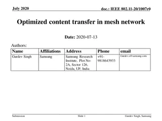
S/N Issue of Mesh APD Changguo Lu, KT McDonald Princeton University 3/2/2016; updated 3/4/2016 1
N. Cartiglia, INFN, Torino, 2/15-19/2016 - 4D tracking Noise in LGAD & APD Aide Memoire According to this argument it raises a series question about the application of APD to the fast timing: LGAD 10~20 gain is better than high gain APD (>100). 2
If the detector can provide good S/N even when its signal is small, we still can use a good amplifier (high gain and low noise figure) to get a large enough signal. We have tested following five commercial amplifiers; obviously, the Wenteq is the best. [The custom amplifier developed at U Penn is even better.] Ampommerlifier Bandwidth( MHz) Gain Noise figure Wenteq ABL0100-01-5010 10 - 1000 50 dB 1.0 dB ZFL-2500+ 500 - 2500 28 dB 6 ~ 8.6 dB ZKL-1R5+ 10 - 1500 40 3.0 dB ZX60-33LN-S+ 50 - 3000 100 1000 2000 3000 1.1 dB 21.9 18.8 14.5 11.9 ZVA-213 800 - 21000 26 2.5 ~ 4.7 dB 3
Test S/N for Mesh APD with Agilent MSO9404A Scope The test circuit used with an RMD 8 8 mm2 APD, with mesh electrode, is the following: Three outputs are connected to scope via SMA cables. The VCSEL 980-nm laser diode is triggered by an HP 8131A pulser with fixed pulse shape; the laser light is transferred via optical fiber to a focusing lens, which is placed in front of APD. The entire APD test box and focusing lens is located inside an environmental chamber, which used primarily as a dark box/Faraday cage. 4
RMS noise of APD signal We noticed that the measured rms noise with digital scope depends on the scope scale used in the measurement (so-called digitization error). We have to understand this behavior first. We leave the scope connected to APD electrode while we change the scope s scale, and observe measured rms noise as follows: 35 y = 0.0301x + 0.0903 30 baseline rms noise(mV) 25 20 15 10 5 0 0 200 400 600 800 1000 1200 Scale(mV/div) The rms noise is linear with the vertical scale of the scope. Of course, if we measure S/N using the scope with the same vertical scale for both signal and rms noise, there is no additional normalization required, and we can directly use the measured signal and rms-noise values in the calculation. 5
S/N of Mesh APD In the plot of S/N and Gain vs. HV below, the S/N ratio is still improving at the maximum HV we have tested, -1800V, which is close to the APD breakdown voltage. The baseline noise is that observed in the full 4-GHz bandwidth of the scope, although fast-timing measurements are made with amplifiers of 500-MHz bandwidth; the results below overestimate the noise relevant to a timing measurement. 100 1000 S/N Gain 1000 100 sig vs gain noise vs gain 100 Gain S/N 10 10 Signal, Noise 10 1 1 1 0.1 0.1 0 500 1000 1500 2000 HV(V) 0.01 0.1 1 10 100 1000 Gain An optimum S/N value of 10-20 is not the case for an RMD APD. The baseline noise rises more slowly than linearly with gain, favoring operation at the highest possible gain. 6
S/N of 22 mm2 APD A signal/noise study of a 2 2 mm2 RMD APD was reported in Fig. 2 of Farrell et al, NIM A353, 176 (1994), using an Fe-55 source. http://physics.princeton.edu/~mcdonald/examples/detectors/farrell_nim_a353_176_94.pdf From Fig 2. of NIM A353, 176 (1994) 100000 Signal 10000 Noise Signal, Noise, S/N S/N 1000 100 10 1 10 100 1000 10000 100000 Gain For gains < 500, the results are similar to those on slide 6 (tho better S/N at a given gain observed on slide 6), while for higher gains the noise rises more quickly with gain (excess noise factor F changes), the S/N drops. The optimum gain is in the range 500-1000, but it is difficult to operate a large RMD APD stabily at such high gain. 7
Should We Consider Noise during the Signal? The goal of the present consideration of noise is to estimate the rms time resolution for pulses in a silicon device according to where N is a relevant rms noise, and S is the pulse signal. , t rise S N = Discussion of noise in silicon devices with gain include a contribution due to fluctuations in the gain process, typically characterized by the excess noise factor F. Should the noise in the above expression for t include the noise during the pulse associated with the excess noise factor? A comparison of the baseline noise (with no signal) to the noise during a pulse of 4500 optical photons incident on a 2 2 mm2 RMD APD is presented in Fig. 8 of Redus and Farrell, PSPIE 2859, 288 (1996), http://physics.princeton.edu/~mcdonald/examples/detectors/redus_spie_2859_288_96.pdf 10000 Fig 8. Redus & Farrell, PSPIE 2859, 288 (1996) Signal, Noise, S/N 1000 Signal 100 Noise (no signal) Noise (in signal) 10 S/N_no_signal S/N_in_signal 1 1 10 100 Gain 1000 10000 The noise during the signal is the rms width of the observed pulse-area distribution. When the noise during the signal is included, the maximum S/N is about 20:1, at gain of 100, for 4500 incident optical photons, whose energy deposition is roughly equivalent to that of 1 minimum-ionizing particle (1 MIP). For the observed rise time rise ~ 1.3 ns in an 8 8 mm2 RMD APD, we observe t ~ 11 ps for a 1-MIP-equivalent pulse of 980-nm photons, http://physics.princeton.edu/~mcdonald/LHC/Lu/Time_resolution_with_beam_splitterE.pptx However, if we use S/N = 20, the prediction would be 65 ps. = riseN S = / t 8 We infer that it is better to use the no-signal noise when estimating time resolution.