Advanced Timer Operations and Clocking in MSP430 LaunchPad
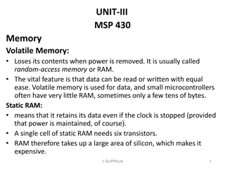
This lab explores advanced timer operations and clocking in MSP430 LaunchPad, focusing on timer characteristics, clock sources, and settings. Topics include Timer_A functions, capture/compare block, clock system details, and modes of operation for timer blocks. The content delves into controlling TAR, TACTL, TACCR0 registers, and utilizing Capture/Compare Blocks for timing events. Learn about various capture modes, actions, interrupts, and signal handling in the context of embedded systems.
Download Presentation

Please find below an Image/Link to download the presentation.
The content on the website is provided AS IS for your information and personal use only. It may not be sold, licensed, or shared on other websites without obtaining consent from the author.If you encounter any issues during the download, it is possible that the publisher has removed the file from their server.
You are allowed to download the files provided on this website for personal or commercial use, subject to the condition that they are used lawfully. All files are the property of their respective owners.
The content on the website is provided AS IS for your information and personal use only. It may not be sold, licensed, or shared on other websites without obtaining consent from the author.
E N D
Presentation Transcript
CS4101 Introduction to Embedded Systems Lab 3: Timer and Clock Prof. Chung-Ta King Department of Computer Science National Tsing Hua University, Taiwan National Tsing Hua University
Introduction In this lab, we will learn more advanced timer operations and clocking of MSP430 LanuchPad Capture/compare block of the timer Characteristics of different clock sources and their settings Clock Timer 1 National Tsing Hua University
Interior of MSP430G2553 Clock system X IO Not available on 20-pin device Timer system 2 National Tsing Hua University
Recall: MSP430 Timer_A TAR (0170h): the counter itself TACTL (0160h): register to control TAR settings TACCR0 (0172h): target for counting Others: clock source selection, flags 3 National Tsing Hua University
Timer_A Capture/Compare Block Timer Block May contain several Capture/Compare Blocks Each C/C block is controlled by a control register, TACCTLx Inside each C/C block, the Capture/Compare Register, TACCRx, holds the count to configure timer But, all C/C blocks within Timer_A share the same timer block: TAR TACTL Capture/Compare Block TACCTL2 4 National Tsing Hua University
Modes of Capture/Compare Block Compare mode: Compare the value of TAR with the value stored in TACCRx and update an output when they match Capture mode: used to record time events Records the time (value in TAR) at which the input changes into TACCRx The input, usually CCIxA and CCIxB, can be either external or internal from another peripheral or software, depending on board connections 5 National Tsing Hua University
Capture Basics 15 0 TAR Counter Overflow Action Interrupt (TAIFG) Counter Register (TAR) Clock Input Clock GPIO Pin (TACLK) Capture Input signal triggers transfer: Counter Capture Capture Actions Interrupt (CCIFGx) Signal peripheral Modify pin (TAx.n) Capture Input CCInA CCInB Software Capture/Compare Register (TACCRx) Capture time (i.e. count value) when Capture Input signal occurs When capture is triggered, count value is placed in CCR and an interrupt is generated 6 National Tsing Hua University
Compare Basics 15 0 TAR Counter Overflow Action Interrupt (TAIFG) Counter Register (TAR) Clock Input Clock GPIO Pin (TACLK) when Counter = Compare Compare Actions can occur Compare Actions Interrupt (CCIFGx) Signal peripheral Modify pin (TAx.n) Capture/Compare Register (TACCRx) 7 National Tsing Hua University
TACCTLx 8 National Tsing Hua University
TACCTL contd 9 National Tsing Hua University
Example of Compare Mode Exact behavior of a Capture/Compare Block depends on setting of the corresponding control register, e.g. TAR counts to TACCR0 and resets (i.e., TACCR0 determines frequency (along with TAR input frequency)) At Output Mode 3, EQU1 is set when TAR>TACCR1 (i.e., TACCR1 determines pulse width) 10 National Tsing Hua University
MSP430 Clock System Clock system 11 National Tsing Hua University
Clock System of MSP430 Variety of oscillator sources: on-chip (cheap, reliable) and off- chip (accurate) Rich selection of oscillator sources routed to internal clocks 12 National Tsing Hua University
Clocks in MSP430 Name MCLK SMCLK ACLK Description Master Clock Sub-Master Clock Peripherals Auxiliary Clock Used-by CPU Typical Speed Fast Fast Slow Peripherals Master clock (MCLK): for CPU and some peripherals, normally driven by digitally controlled oscillator (DCO) Subsystem master clock (SMCLK): distributed to peripherals, normally driven by DCO Auxiliary clock (ACLK): distributed to peripherals, normally for real-time clocking and driven by a low-frequency crystal oscillator, typically at 32 KHz 13 National Tsing Hua University
Clock Sources Low- or high-frequency crystal oscillator, LFXT1: External; used with a low- or high frequency crystal; an external clock signal can also be used; connected to MSP430 through XIN and XOUT pins High-frequency crystal oscillator, XT2: External; similar to LFXT1 but at high frequencies Very low-power, low-frequency oscillator, VLO: Internal at 12 KHz; alternative to LFXT1 when accuracy of a crystal is not needed; may not available in all devices Digitally controlled oscillator, DCO: Internal; a highly controllable RC oscillator that starts fast 14 National Tsing Hua University
Controlling Clocks In MSP430, the Basic Clock Module is also an IO peripheral and can be controlled by registers, DCOCTL and BCSCTL1 3 DCOCTL (056h): configure DCO BCSCTL1 (basic clock system control 1, 057h): configure ACLK BCSCTL2 (basic clock system control 2, 058h): configure MCLK, SMCLK BCSCTL3 (basic clock system control 3, 053h): control LFXT1/VLO 15 National Tsing Hua University
DCOCTL (at Memory Address 056h) Tag-Length-Value DCOCTL = CALDCO_1MHZ; // Set DCO step + modulation 16 National Tsing Hua University
Tag-Length-Value Tag-Length-Value (TLV) stores device-specific information in the flash memory to set DCOCTL and BCSCTL1 for DCO frequency BCSCTL1 = CALBC1_1MHZ; DCOCTL = CALDCO_1MHZ; // Set range 17 National Tsing Hua University
BCSCTL1 BCSCTL1 = CALBC1_1MHZ; // Set range 18 National Tsing Hua University
BCSCTL2 MCLK SMCLK BCSCTL2 |= SELM_3 + DIVM_3; // MCLK = VLO/8 19 National Tsing Hua University
BCSCTL3 In MSP430G2231 BCSCTL3 |= LFXT1S_2; // Enable VLO as MCLK/ACLK src 20 National Tsing Hua University
Interrupt Flag Register 1 (IFG1) OFIFG oscillator-fault flag is set when an oscillator fault (LFXT1OF) is detected. IFG1 &= ~OFIFG; // Clear OSCFault flag 21 National Tsing Hua University
Sample Code for Timer_A Flash red LED at 1 Hz using SMCLK at 800 KHz #include <msp430g2553.h> #define LED1 BIT0 void main (void) { WDTCTL = WDTPW|WDTHOLD; // Stop watchdog timer P1OUT = ~LED1; P1DIR = LED1; TACCR0 = 49999; TACTL = MC_1|ID_3|TASSEL_2|TACLR; //Setup Timer_A //up mode, divide clk by 8, use SMCLK, clr timer for (;;) { // Loop forever while (!(TACTL&TAIFG)) { // Wait time up } // doing nothing TACTL &= ~TAIFG; // Clear overflow flag P1OUT ^= LED1; // Toggle LEDs } // Back around infinite loop } 22 National Tsing Hua University
Lab 3 Basic 1: Flash both red and green LEDs at 1 Hz. The green LED should be on for 0.7 sec and off for 0.3 sec, which is controlled by polling Timer0_A driven by ACLK sourced by VLO. The red LED should be on for 0.2 sec and off for 0.8 sec, which is controlled by polling Timer1_A driven by SMCLK sourced by DCO. Basic 2: Repeat Basic 1 by using Timer0_A only. Use TA0R to keep a cycle time of 1 sec. Use TA0CCR1 to control the green LED and TA0CCR2 to control the red LED. 23 National Tsing Hua University
Lab 3 Bonus: Flash the green LED at 1 Hz by polling Timer0_A, on for 0.5 sec and off for 0.5 sec. When the button is pressed, keep the green LED at the same state, and turn on the red LED with a proportion of time according to the time the button is pressed e.g., when the button is pressed for less than 1 sec, then turn on the red LED for 0.1 sec and off for 0.9 sec; when the button is pressed for more than 1 sec but less than 2 sec, then turn on the red LED for 0.2 sec and off for 0.8 sec, etc. Hint: use the timer for green LED to track button timing If the button is pressed for more than 5 sec, then turn off the red LED. 24 National Tsing Hua University
