Advanced Virtual Manufacturing and Power Electronics Training Courses in January 2025
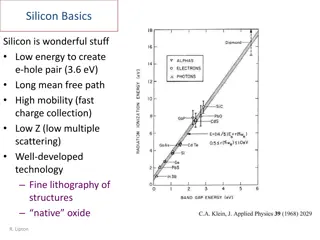
Explore cutting-edge virtual manufacturing and power electronics training courses integrating TCAD-based processes for optimized design and manufacturing. Funded by IUK, this project delves into physical constants, basic relations, semiconductor materials, and manufacturing techniques. Dive deep into the world of Si, Ge, and B elements, their abbreviations, and definitions in the realm of power electronics design and manufacturing.

Download Presentation

Please find below an Image/Link to download the presentation.
The content on the website is provided AS IS for your information and personal use only. It may not be sold, licensed, or shared on other websites without obtaining consent from the author. If you encounter any issues during the download, it is possible that the publisher has removed the file from their server.
You are allowed to download the files provided on this website for personal or commercial use, subject to the condition that they are used lawfully. All files are the property of their respective owners.
The content on the website is provided AS IS for your information and personal use only. It may not be sold, licensed, or shared on other websites without obtaining consent from the author.
E N D
Presentation Transcript
Virtual Manufacturing Based Power Electronics Design and Manufacturing Training Courses TCAD based process integration/optimisation January 2025
Physical constants and basic relations This project is funded by IUK under grant agreement application number:10033153 2
Symbol Si Ge B Element name Silicon Germenium Boron Abbreviation ECR RF MOCVD Definition Electron cyclotron resonance Radio Frequency Metal-Organic Chemical Vapor Deposition Abbreviation LPCVD ALD ESD BCA RIE CMP VLSI SD DD VFTA TFVA ILD ORS IGBT Definition Low pressure CVD Atomic Layer Deposition Electrostatic Discharge Binary Collision Approximation Reactive Ion Etching Chemical Mechanical Polishing Very Large-Scale Integration Single-damascene Double-damascene Via-Frst-Trench-After Trench-First_Via_After Interlayer dielectric deposition Oxygen Retarded Silicidation Insulated-gate bipolar transistor Vertical Double-diffused Metal Oxide Semiconductor Field Effect Transistor vertical trench U-shape metal-oxide- semiconductor field-effect-transistors bipolar junction transistor Wcell P As W T Al Phosphorus Arsenic Tungsten Titanium Aluminium HRXRD FWHM KMC CVD LTCVD MOCVD PECVD HTCVD UVCVD APCVD EBPCV STI Poly-Si High-resolution X-ray diffraction Full width at half maximum Kinetic Monte Carlo chemical vapor deposition Low-Temperature Chemical Vapor Deposition Metal-Organic Chemical Vapor Deposition Plasma-enhanced chemical vapor deposition High Temperature CVD ultraviolet chemical vapor deposition Atmospheric Pressure CVD electron beam CVD Shallow Trench Isolation Polysilicon (highly doped Gate material) It is a processing technique in which several processes are carried out in sequence without exposing the wafer to air between the process steps Compound SiO2 SiC GaN InN AlN AlInGan InGaN AlGaN NH3 Al2O3 C2H4 SiH4 TiSi2 TaSi2 MoSi2 CoSi2 WSi2 PtSi2 TiN Compound Name Silicon Dioxide Silicon Carbide Gallium nitride Indium Nitride Aluminum Nitride Amonia Indium Galium Nitride Aluminum Gallium Nitride Hydride Ammonia Sapphire Ethylene silane Titanium disilicide Tantulum Silicide Molybdenum disilicide Cobalt disilicide Tungston Disilicide Platinum Disilicide Titanium nitride VDMOSFET UMOSFET BJT Cell width Epi thickness/doping Depi/Nepi Gate width Gate oxide thickness dox N+ implant mask opening N+ junction depth P-body implant mask opening P-body junction depth Xjp Channel length In-situ RCA (Radio Corporation of America) Cleaning WG A standard type of cleaning wafer before major process steps Wi electronic grade Tetraethyl Orthosilicate is a chemical compound used for thin insulating layers Floating guard rings Junction termination extension Beveled structure of the edge Xjn Wp TEOS FGR JTE Mesa Lch This project is funded by IUK under grant agreement application number:10033153 3
Silicon power VD_DIODE-2D Center of the Device This project is funded by IUK under grant agreement application number:10033153 This project is funded by IUK under grant agreement application number:10033153 4
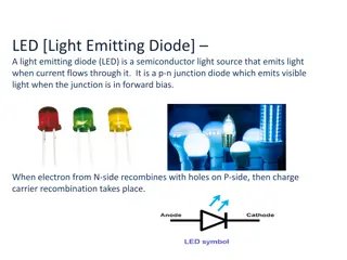
Introduction Silicon power diodes with breakdown voltages in the range of 30 5000V are essential components for power converters, inverters and motor drives. However, due to significant power losses related to reverse recovery they are progressively replaced by SiC diodes.. Lifetime killing is used in very high voltage Si power diodes to speed up the reverse recovery transient. This project is funded by IUK under grant agreement application number:10033153 5
Device structure The drift region (? ?????) absorbs the depletion layer of the reverse biased pn junction. In forward bias condition it appears as a series resistance modifying the diode I-V characteristics. (A) (A) ?+ (A) (A) ?+ Same device ? 100 m ? 4e13 ?? 3 4e13 ?? 3 100 m 1e20 ?? 3 (K) (K) ?+ 5 m 1e20 ?? 3 ?+ 5 m (K) (K) This project is funded by IUK under grant agreement application number:10033153 6
VD Si Diode process steps Semiconductor wafer Starting material: N+ bottom layer (cathode for PiN, layer - Thick=5 um, doping=1e20cm-3). Initial substrate N++: As, ?=0.0028 ?.cm, Orient=<100> N+ Sub N++ Substrate N++ Substrate This project is funded by IUK under grant agreement application number:10033153 7
VD Si Diode process steps Semiconductor wafer Starting material:Epitaxial Growth Module, N- epilayer over N+ layer start with doping ~ 4e13cm-3 and thick=100um N- Epi N+ Sub Schematics Process Generated N- epi N- epi N++ Substrate N++ Substrate This project is funded by IUK under grant agreement application number:10033153 8
1D Doping Profile This project is funded by IUK under grant agreement application number:10033153 9
VD Si Diode process steps Semiconductor Oxidation: Pre-clean, SiO2 deposition 2000Angs thermal oxidation, deposit Oxide type= isotropic thickness= 0.2<um> N- Epi N+ Sub SiO2 Schematics Process Generated N- epi N- epi N++ Substrate N++ Substrate This project is funded by IUK under grant agreement application number:10033153 10
VD Si Diode process steps Semiconductor Nitride: Nitride deposition 0.9 um, deposit nitride thickness =0.9<um> iso. N- Epi N+ Sub SiO2 Si3N4 Schematics Process Generated N- epi N- epi N++ Substrate N++ Substrate This project is funded by IUK under grant agreement application number:10033153 11
VD Si Diode process steps Semiconductor Photo: Photo resist. mask name= ANODEL left= 0<um> right= 3<um> photo mask= ANODEL thickness= 1 N- Epi N+ Sub SiO2 Si3N4 Schematics Process Generated Resist N- epi N- epi N++ Substrate N++ Substrate This project is funded by IUK under grant agreement application number:10033153 12
VD Si Diode process steps Depo Resist /Nitride etch: Nitride etch, RIE etch, resist clean, etch material= {nitride} type= anisotropic time= 1 rate= {0.9} N- Epi N+ Sub SiO2 Si3N4 Schematics Process Generated Resist N- epi N- epi N++ Substrate N++ Substrate This project is funded by IUK under grant agreement application number:10033153 13
VD Si Diode process steps Oxide etch: Pre clean, Oxide etch. etch material= {Oxide} type= anisotropic time= 1 rate= {0.2} N- Epi N+ Sub SiO2 Si3N4 Schematics Process Generated Resist N- epi N- epi N++ Substrate N++ Substrate This project is funded by IUK under grant agreement application number:10033153 14
VD Si Diode process steps Strip photo: Photo resist strip, strip photo. N- Epi N+ Sub SiO2 Si3N4 Schematics Process Generated N- epi N- epi N++ Substrate N++ Substrate This project is funded by IUK under grant agreement application number:10033153 15
VD Si Diode process steps Implant P+ (Boron) : The implantation mask opening for P+ implant: -15um/5um, P+ anode layer: Implantation of B: dose ~2-3e15cm-2, Energy~200keV, Annealing 130 min 1150 C N- Epi N+ Sub SiO2 P+ Si3N4 Schematics Process Generated N- epi N- epi N++ Substrate N++ Substrate This project is funded by IUK under grant agreement application number:10033153 16
1D Vertical Doping Profile This project is funded by IUK under grant agreement application number:10033153 17
Implanted and Active concentration This project is funded by IUK under grant agreement application number:10033153 18
VD Si Diode process steps Remove Resist/Deposition ILD:Resist strip/clean, ILD deposition TEOS (Tetraethyl Orthosilicate) 6.6 kA Furnace. N- Epi N+ Sub SiO2 P+ Si3N4 Schematics Process Generated ILD N- epi N- epi N++ Substrate N++ Substrate This project is funded by IUK under grant agreement application number:10033153 19
VD Si Diode process steps Resist/Photo Contact Anode: Photo resist, mask name= ANODEL2 left= 0<um> right= 3<um>, photo mask= ANODEL2 thickness= 1 N- Epi N+ Sub SiO2 P+ Si3N4 Schematics Process Generated ILD N- epi Resist N- epi N++ Substrate N++ Substrate This project is funded by IUK under grant agreement application number:10033153 20
VD Si Diode process steps Etch Resist/ILD: RIE etching of ILD, Etch ILD, etch material= {ILD} type= isotropic time= 1 rate= {1.5} N- Epi N+ Sub SiO2 P+ Si3N4 Schematics Process Generated ILD N- epi Resist N- epi N++ Substrate N++ Substrate This project is funded by IUK under grant agreement application number:10033153 21
VD Si Diode process steps Resist//Remove Resist: Resist strip, clean N- Epi N+ Sub SiO2 P+ Si3N4 Schematics Process Generated ILD N- epi N- epi N++ Substrate N++ Substrate This project is funded by IUK under grant agreement application number:10033153 22
VD Si Diode process steps Deposition Metal Al/Cu: deposit material= {Aluminum} type= isotropic time= 1 rate= {2.4} N- Epi N+ Sub SiO2 P+ Si3N4 Schematics Process Generated ILD N- epi Metal N- epi N++ Substrate N++ Substrate This project is funded by IUK under grant agreement application number:10033153 23
VD Si Diode process steps Deposition Insulator/Passivation: Deposition Thick Insulator 2.6um,deposit Insulator thickness =2.6<um> iso N- Epi N+ Sub SiO2 P+ Si3N4 Schematics Process Generated ILD N- epi Metal Passivation N- epi N++ Substrate N++ Substrate This project is funded by IUK under grant agreement application number:10033153 24
Breakdown of the Center of the device This project is funded by IUK under grant agreement application number:10033153 25
Forward-Reverse Bias ???? Break down voltage TCAD I V Characteristic This project is funded by IUK under grant agreement application number:10033153 26
Transients This project is funded by IUK under grant agreement application number:10033153 27
Transients This project is funded by IUK under grant agreement application number:10033153 28
Silicon power VD_DIODE-3D Simulation This project is funded by IUK under grant agreement application number:10033153 This project is funded by IUK under grant agreement application number:10033153 29
3D Cylindrical Simulations Purpose: Simulate the breakdown voltage (BV) characteristics under various conditions. Evaluate the influence of the radius on BVs. Breakdown Voltage: The BV will depend on the doping concentration and thickness of the N- drift region, alongside the radius. Larger radii may experience edge effects and reduced breakdown due to field crowding at the boundaries. Field Distribution: Electric field is highest near the P+ and N- interface. Proper doping and design minimize premature breakdown. This project is funded by IUK under grant agreement application number:10033153 30
3D Cylindrical Simulations 2D representation of the model 3D representation of the model This project is funded by IUK under grant agreement application number:10033153 31
P+ Radius = 5um P+ Radius = 20um P+ Radius = 10um Simulated TCAD structures: P+ Radius = 30um P+ Radius = 80um P+ Radius = 50um P+ Radius = 100um
100um 5um BVs BVs increased at higher P+ radius values and decreased at lower P+ radius
Electric field is highest near the P+ and N- interface Anode, P+ region Cathode, N+ region
Anode, P+ region Cathode, N+ region
Thank You! https://www.semiconductorwise.com 2013-2025 Semiwise Limited, Company number SC465719 - VAT number 281269391