Advanced x86 BIOS and System Management Internals Memory Map

This content delves into the intricacies of the BIOS, memory mapping, and system management processes for the x86 architecture. It covers aspects like memory programming, system memory ranges, memory mapping responsibilities, and hardware block diagrams. Exploring BIOS setup, memory configurations, and chipset mapping intricacies are key focuses ."

Download Presentation

Please find below an Image/Link to download the presentation.
The content on the website is provided AS IS for your information and personal use only. It may not be sold, licensed, or shared on other websites without obtaining consent from the author.If you encounter any issues during the download, it is possible that the publisher has removed the file from their server.
You are allowed to download the files provided on this website for personal or commercial use, subject to the condition that they are used lawfully. All files are the property of their respective owners.
The content on the website is provided AS IS for your information and personal use only. It may not be sold, licensed, or shared on other websites without obtaining consent from the author.
E N D
Presentation Transcript
Advanced x86: BIOS and System Management Mode Internals Memory Map Xeno Kovah && Corey Kallenberg LegbaCore, LLC
All materials are licensed under a Creative Commons Share Alike license. http://creativecommons.org/licenses/by-sa/3.0/ Attribution condition: You must indicate that derivative work "Is derived from John Butterworth & Xeno Kovah s Advanced Intel x86: BIOS and SMM class posted at http://opensecuritytraining.info/IntroBIOS.html 2
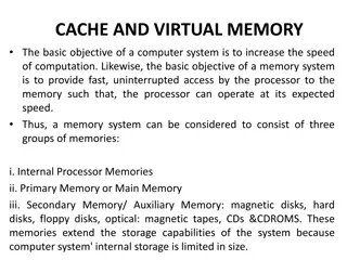
Memory Map One of the primary responsibilities of the BIOS is to program the memory map Many devices, in order to be useful, require their interfaces be extended to memory Also this is how the BIOS can ensure information about the way it set up the system is passed to the operating system at the time of handoff 3
4 Basic Ranges in System Memory TOUUD TOM TOLUD 1. High Memory Range: Memory above 4GB (called Top of Upper Usable DRAM). Used for memory mapping and recoverable memory (system memory that overlaps with the PCI range) TOM (Top of Upper Memory): size of physical memory PCI Memory Address Range: Used for memory-mapped IO (TPM, APIC, Flash, PCI Express, devices on chipset, etc.) Main Memory Address Range: Addressable memory from TOLUD (Top of Low Usable DRAM) down to 1 MB Compatible Memory space: 1 MB and below 2. 3. 4. 4
Memory Map TOM But on startup the processor is only aware of one memory range as we ve seen Often called the Boot Block, it contains the entry vector and uncompressed BIOS code The system automatically maps the top 16 MB of memory to the flash bios Non-negotiable, does not matter if your system has < 4 GB of memory, the system never actually accesses that memory. Rather, it is mapped to the flash device. The rest of system memory needs to be configured by the BIOS FFFF_0000 5
Hardware Block Diagram FFFF_FFFFh Chipset FEDA_0000h DRAM Controller B0:D0:F0 Offset Name Value F800_0000h 48h MCHBAR FEDA0000h DRAM Controller B0:D0:F0 Offset Name Value 60h PCIEXBAR F8000000h 0000_0000h On the Mobile 4-Series Chipset, the BIOS (executed by the CPU), configures the MCHBAR in the DRAM Controller FEDA_0000h (on an E6400 with 4GB RAM for example) MCHBAR is now added to the memory map So how does this actually occur? 6