Amplifier Circuits and Functions
Explore the basic concepts of amplifiers, including their function, types of gain, and signal processing abilities. Learn how amplifiers preserve the quality of analog signals by adjusting their amplitudes. Understand the significance of voltage gain and power gain in amplifier circuits.

Download Presentation

Please find below an Image/Link to download the presentation.
The content on the website is provided AS IS for your information and personal use only. It may not be sold, licensed, or shared on other websites without obtaining consent from the author. If you encounter any issues during the download, it is possible that the publisher has removed the file from their server.
You are allowed to download the files provided on this website for personal or commercial use, subject to the condition that they are used lawfully. All files are the property of their respective owners.
The content on the website is provided AS IS for your information and personal use only. It may not be sold, licensed, or shared on other websites without obtaining consent from the author.
E N D
Presentation Transcript
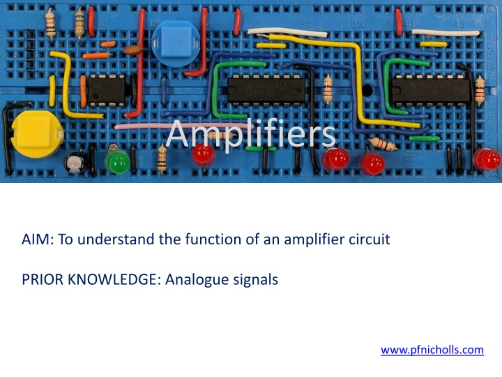
Amplifiers AIM: To understand the function of an amplifier circuit PRIOR KNOWLEDGE: Analogue signals www.pfnicholls.com
Introduction Amplifiers are active (needing a power supply) devices that process analogue signals. Analogue signals are signals that vary with time and can take any value between some maximum and some minimum value. Analogue signals can be both positive and negative. The symbol for an amplifier is very similar to that of a NOT gate and intentionally the same as a buffer Be careful not to get them confused. The symbol shown is for a non- inverting amplifier with a gain of x10
The Basic Amplifier The purpose of an amplifier is to accept an analogue input signal and produce a copy of the signal at the output. The shape (quality) and frequency of the amplified input signal should not change at all at the output. Any change of shape is called distortion and is usually avoided as much as possible. The amplitude of the output can be different from the amplitude of the input signal. The scaling factor is called the gain. If the resulting output signal is bigger than the input signal then it has been amplified. If the resulting output signal is smaller than the input signal then it has been attenuated. In both cases the change in the size of the signal is described by the amplifier gain.
Gain Amplifiers are considered in terms of: Voltage gain (Gv or Av) Open loop gain (A0) power gain (Gp or Ap) In general terms, voltage gain is defined as: Voltage Gain = Vout / Vin The open loop gain is the natural gain of the amplifier when no feedback is applied. This is usually very high. The power gain is defined as the ratio of output power to input power: Power Gain = Pout / Pin
Gain Original signal On the graph, the x-axis is time Signal after a gain of + 2 The y-axis is either voltage or power depending on which gain is being shown Signal after a gain of 1.5 Signal after a gain of + 0.5
Gain The voltage gain is purely a number being the ratio of two voltages. In real terms the voltage gain is the amount by which an input voltage is multiplied to give an output voltage A gain of + 50 means that the output voltage is 50 times greater than the input voltage A gain of 50 means that the output voltage is 50 times greater than the input voltage and negative for a positive input (the input is inverted) A gain of + 0.5 means that the output voltage is half as big as the input voltage (the signal is attenuated) A gain of + 1 means that the output voltage is equal to the input voltage (unity gain)
Distortion Distortion occurs when the output signal is not a true copy (albeit amplified or attenuated) of the input signal. The most common form of distortion occurs when the gain and/or input voltage are too high and the resulting output signal is (theoretically) greater than the maximum possible output voltage. The maximum possible output voltage is determined by the power supply voltages of the amplifier. For example, a standard op-amp based amplifier has power supplies of 15 V and a maximum output voltage of 13 V. Consider an amplifier with a gain of +10. For an input voltage of +1.0 V, the output voltage will be +10 V and the output is not distorted. For an input voltage of +2.0 V, the output voltage will try to be +20 V but will be limited to +13 V. The input signal is distorted.
Distortion An amplifier has a maximum output voltage of 13 V shown by the dotted ORANGE line on the diagram. The input voltage is 5 V as shown by the BLUE line.
Distortion When the amplifier gain is +2, the output is 10 V as shown by the GREEN line. This is less than the maximum output voltage and the input signal is amplified but not distorted.
Distortion When the amplifier gain is increased to +3 the output voltage should be 15 V but it is limited to 13 V by the power supply. The output is the RED line with the peaks of the output flattened off. The input signal is amplified but the output is not the same shape as the input. The output is distorted.
Bandwidth The bandwidth is the range of frequencies over which the amplifier circuit produces at least half of its rated output power For example, an audio amplifier would have a bandwidth of at least 20 Hz to 20 kHz as this is the audible spectrum Bandwidth is usually shown on a graph of frequency against power with either or one or both axes being logarithmic.
Bandwidth It is important to realise that the bandwidth is expressed in terms of power. Power can be expressed in terms of voltage and current, P = V2 / R We can also find a definition of bandwidth in terms of voltage. The power is proportional to V2 and so P/2 is proportional to ( V2 )/2 which implies that half power is achieved when the output voltage is reduced to V/(sqrt(2)) = 0.707 x V
Bandwidth The bandwidth is the range of frequencies over which the amplifier circuit produces at least half of its rated output power The bandwidth is the range of frequencies over which the amplifier circuit produces at least 0.7 of its rated output voltage The bandwidth is the range of frequencies over which the voltage gain is greater than 0.7 of the expected voltage gain
Testing Amplifiers An amplifier can be tested using the circuit shown. A signal generator is connected to the input. This provides a signal of variable amplitude and frequency. One channel of a double beam oscilloscope is attached to the input so that the input voltage can be determined (usually kept fixed at a convenient value). The other channel of the double beam oscilloscope is connected to the output (which may or may not be connected to a load such as a loudspeaker) and is used to measure the output voltage.
Testing Amplifiers To test the amplifier a range of frequencies is used For an audio amplifier the frequencies used for testing might be 10 Hz, 20 Hz, 30 Hz, 50 Hz, 70 Hz and then 100 Hz, 200 Hz and so on up to 10 kHz, 20 kHz, 30 kHz, 50 kHz etc This choice of frequencies gives a nice even spread on a logarithmic scale
Summary Amplifiers produce a copy of the input signal with the same frequency and shape but a different amplitude Gain is the factor by which the amplitude of the signal is changed Voltage gain = Output voltage Input voltage Power gain = Output power Input power The signal may be amplified (Gain > 1) or attenuated (Gain < 1) or remain unchanged (Gain = 1) An inverting amplifier produces a negative output for a positive input Distortion occurs when the output signal is not the same shape as the input signal Bandwidth is the range of frequencies for which the amplifier produces at least half the expect output power
Questions 1. An amplifier produces an output of 5 V for an input of 1 V. What is the amplifier gain? 2. An input of 100 mV results in an output of 20 V. What is the gain of the amplifier? 3. An input of 2 V results in an output of 0.5 V. What is the gain of the amplifier? 4. An amplifier gain is + 12. What is the output voltage for an input of 200 mV? 5. An amplifier has a gain of + 10 and a maximum output voltage of 15 V. What is the output voltage for an input voltage of (a) 1.0 V, (b) 2.0 V and (c) 3.0 V
Answers 1. + 5 (not just 5) 2. 200 ( 20 / 0.1 as 100 mV is 0.1 V) 3. + 0.25 4. 2.4 V 5. (a) 10 V (b) 15 V (c) 15 V For (b) and (c) the output is distorted due the limitations of the power supply