Explore the difference between analog and digital signals, their reliability, and the concept of binary numbering systems. Discover how electronic circuits and transistors handle these signals, and delve into the fundamentals of counting in decimal and binary systems.
Please find below an Image/Link to download the presentation.
The content on the website is provided AS IS for your information and personal use only. It may not be sold, licensed, or shared on other websites without obtaining consent from the author. If you encounter any issues during the download, it is possible that the publisher has removed the file from their server.
You are allowed to download the files provided on this website for personal or commercial use, subject to the condition that they are used lawfully. All files are the property of their respective owners.
The content on the website is provided AS IS for your information and personal use only. It may not be sold, licensed, or shared on other websites without obtaining consent from the author.
E N D
Presentation Transcript
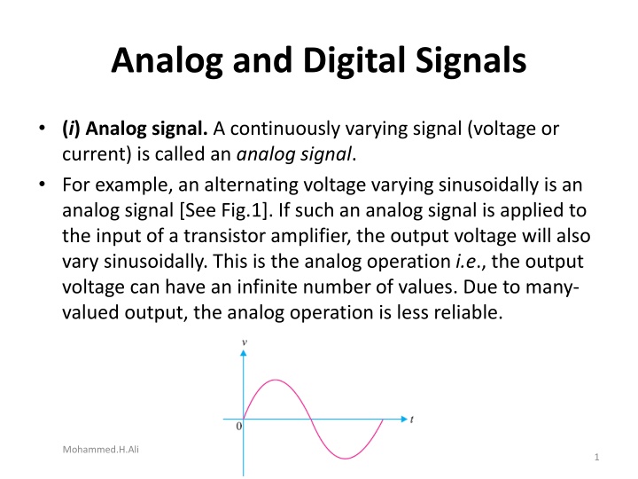
Analog and Digital Signals (i) Analog signal. A continuously varying signal (voltage or current) is called an analog signal. For example, an alternating voltage varying sinusoidally is an analog signal [See Fig.1]. If such an analog signal is applied to the input of a transistor amplifier, the output voltage will also vary sinusoidally. This is the analog operation i.e., the output voltage can have an infinite number of values. Due to many- valued output, the analog operation is less reliable. Mohammed.H.Ali 1
ii) Digital signal. A signal (voltage or current) that can have only two discrete values is called a digital signal. For example, a square wave is a digital signal [See Fig.2]. It is because this signal has only two values viz, +5 V and 0 V and no other value. These values are labeled as High and Low. The High voltage is + 5 V and the Low voltage is 0 V. If proper digital signal is applied to the input of a transistor, the transistor can be driven between cut off and saturation. In other words, the transistor will have two-state operations i.e., output is either low or high. Since digital operation has only two states (i.e., ON or OFF), it is far more reliable than many-valued analog operation. It is because with two states operation, all the signals are easily recognized as either low or high. 2 Mohammed.H.Ali
Digital Circuit An electronic circuit that handles only a digital signal is called a digital circuit. The output voltage of a digital circuit is either low or high and no other value. In other words, digital operation is a two-state operation. These states are expressed as (High or Low) or (ON or OFF) or (1 or 0). Therefore, a digital circuit is one that expresses the values in digits 1 s or 0 s. Hence the name digital. The numbering concept that uses only the two digits 1 and 0 is the binary numbering system. Therefore, the first step would be to discuss this number system. Mohammed.H.Ali 3
Binary Number System A number system is a code that uses symbols to count the number of items. The most common and familiar number system is the decimal number system. The decimal number system uses the symbols 0, 1, 2, 3, 4, 5, 6, 7, 8 and 9. Thus, the decimal system uses 10 digits for counting the items. A binary system uses only two digits (0 and 1) for counting the items. The reader may wonder how to count the items in a binary system. Mohammed.H.Ali 4
Counting in Decimal and Binary systems Figure.3 shows the counting of stones in decimal as well as binary system. As you will see, the counting in the binary number system is performed much the same way as in the decimal number system. Mohammed.H.Ali 5
i) Let us first see how items are counted in decimal system. In this system, the count starts as 0, 1, ...., 9. After 9, we are to write the next number. To do so, we use the second digit of the decimal system (i.e., 1) followed by the first digit (i.e., 0). So after 9, the next number is 10. In order to represent a number next to 99, we use three decimal digits (100). That is to say second digit of the decimal system (i.e., 1) followed by two first digits (i.e, two zeros). Mohammed.H.Ali 7
binary system ii) Let us now turn to binary system. Note that 0 and 1 count in the binary system is the same as in the decimal counting. To represent 2 stones, we use the second binary digit (i.e., 1) followed by the first (i.e., 0). This gives binary number 10 (read as one-zero and not ten) as an equivalent of 2 in the decimal system. After this, the two binary digits are exhausted. We shall use three digits to represent the next binary number. Thus, to represent 4 (four), we use the second binary digit followed by two first binary digits. This gives the binary *100 (read as one-zero-zero) as equivalent to 4 in the decimal system. Mohammed.H.Ali 8
Notes (i) Each binary digit (0 or 1) is referred to as a bit. A string of four bits is called as a nibble and eight bits make a byte. Thus, 1001 is a nibble and 10010110 is a binary byte. (ii) The binary number system is the most useful in digital circuits because there are only two digits (0 and 1). Mohammed.H.Ali 9
Place Value Consider the decimal number 642. This can be expressed as : 642 = 600 + 40 + 2 Note that in a multi digit decimal number (i.e., 642 in the present case), each position has a value that is 10 times the value of the next position to its immediate right. In other words, every position can be expressed as : 642 = 6 102 + 4 101 + 2 100 Thus, we find that values of various positions in a decimal number system are powers of 10 Mohammed.H.Ali 10
LSD & MSD For the decimals, the digit to the extreme right is referred to as the least significant digit (LSD) because its positional value or weight is the lowest. For the decimal number 642, 2 is the LSD. The left-most digit in the decimal number is the most significant digit (MSD) because its positional value or weight is the highest. Mohammed.H.Ali 11
Binary-Coded Decimal Code (BCD Code) In a BCD code, each decimal number is represented by a 4-bit binary number. For example, to convert decimal number (489)10 to BCD, the procedure is as under : 4 8 9 0100 1000 1001 Mohammed.H.Ali 13
Encoders and Decoders i) Convert the information from decimal to digital (binary) form. (ii) Process the digital information. (iii) Convert the digital output back to decimal form. The circuit that converts decimal form to digital (binary) form is called encoder and the circuit that converts digital form to decimal form is called decoder. Mohammed.H.Ali 16
Advantages and Disadvantages of Digital Electronics The world of electronics can be classified as either digital or analog circuits. An increasing majority of applications in electronics use digital techniques to perform operations that were once performed using analog methods. It is worthwhile to give advantages and disadvantages of digital electronics. Advantages. The chief reasons for the shift to digital technology are : (i) Digital systems are generally easier to design. It is because the circuits that are used are switching circuits where exact values of voltages or currents are not important, only the range (HIGH or LOW) in which they fall is important. (ii) Digital circuits provide greater accuracy and precision. It is because digital circuits can handle as many digits of precision as you need simply by adding more switching circuits. In analog systems, precision is usually limited to three or four digits because the values of voltage and current are directly dependent on the circuit components. Mohammed.H.Ali 18
Advantages (iii) Digital circuits are less affected by noise. Suprious fluctuations in voltage (noise) are not as critical in digital systems as in analog systems. It is because in a digital circuit, the exact value of a voltage is not important as long as the noise is not large enough to prevent us from distinguishing a HIGH from a LOW. (iv) More digital circuitry can be fabricated on IC chips. Analog system uses such devices (high-value capacitors, inductors, transformers) that cannot be economically integrated. For this reason, analog systems cannot achieve the same degree of integration as digital circuits. (v) Information storage is easy with digital circuits. Mohammed.H.Ali 19
Disadvantages (i) The real world is mainly analog. However, the digital circuits can handle only digital signals. This necessitates encoders and decoders which increase the cost of the equipment. (ii) There are situations where using only analog techniques is simpler and more economical. For example, the process of signal amplification is most easily accomplished using analog circuitry. However, advantages of digital techniques outweigh the disadvantages. For this reason, we are fast switching to digital techniques. Mohammed.H.Ali 20
The Shift Register The Shift Register is another type of sequential logic circuit that can be used for the storage or the transfer of data in the form of binary numbers. This sequential device loads the data present on its inputs and then moves or shifts it to its output once every clock cycle, hence the name shiftregister Mohammed.H.Ali 21
The Shift Register A shift register basically consists of several single bit D-Type Data Latches , one for each data bit, either a logic 0 or a 1 , connected together in a serial type daisy-chain arrangement so that the output from one data latch becomes the input of the next latch and so on. Mohammed.H.Ali 22
Shift Registers are used for data storage or for the movement of data and are therefore commonly used inside calculators or computers to store data such as two binary numbers before they are added together, or to convert the data from either a serial to parallel or parallel to serial format Mohammed.H.Ali 23
Types of shift register Serial-in to Parallel-out (SIPO) - the register is loaded with serial data, one bit at a time, with the stored data being available at the output in parallel form. Serial-in to Serial-out (SISO) - the data is shifted serially IN and OUT of the register, one bit at a time in either a left or right direction under clock control. Parallel-in to Serial-out (PISO) - the parallel data is loaded into the register simultaneously and is shifted out of the register serially one bit at a time under clock control. Parallel-in to Parallel-out (PIPO) - the parallel data is loaded simultaneously into the register, and transferred together to their respective outputs by the same clock pulse. Mohammed.H.Ali 24
Integrated circuit (ICs) While there are many ICs containing only digital circuits and many that contain only linear circuits, there are a number of units that contain both linear and digital circuits. Among the linear/digital ICs are comparator circuits, digital/analog converters, interface circuits, timer circuits, voltage controlled oscillator (VCO) circuits, and phase locked loops (PLLs). Mohammed.H.Ali 26
Circuits that convert digital signals into an analog or linear voltage, and those that convert a linear voltage into a digital value, are popular in aerospace equipment, Automotive equipment, and compact disk (CD) players, among many others Mohammed.H.Ali 28
Timer ICs provide linear and digital circuits to use in various timing operations, as in a car alarm, a home timer to turn lights on or off, and a circuit in electromechanical equipment to provide proper timing to match the intended unit operation. The 555 timer has long been a popular IC unit Mohammed.H.Ali 29
COMPARATOR UNIT OPERATION A comparator circuit accepts input of linear voltages and provides a digital output that indicates when one input is less than or greater than the second. A basic comparator circuit can be represented as in Fig. 17.1a. The output is a digital signal that stays at a high voltage level when the noninverting (+) input is greater than the voltage at the inverting (-) input and switches to a lower voltage level when the noninverting input voltage goes below the inverting input voltage Figure 17.1 Comparator unit: (a) basic unit; Mohammed.H.Ali 30
Figure 17.1b shows a typical connection with one input . As long as Vin is less than the reference voltage level of 2 V, the output remains at a low voltage level (near 10 V). When the input rises just above 2 V, the output quickly switches to a high-voltage level (near 10 V). Thus the high output indicates that the input signal is greater than 2 V. Figure 17.1 Comparator unit: (b) typical application. Mohammed.H.Ali 31
we can examine the operation of a comparator using a 741 op-amp, as shown in Fig. 17.2. With reference input (at pin 2) set to 0 V, a sinusoidal signal applied to the noninverting input (pin 3) will cause the output to switch between its two output states, as shown in Fig. 17.2b Mohammed.H.Ali 32


 Digital signal. A signal (voltage or current) that can")


 Let us first see how items are counted in decimal")


")


