Analog Output and PWM in Physical Computing
Explore the concept of analog output and Pulse Width Modulation (PWM) in physical computing. Learn how to generate analog voltage using digital pins and control LED brightness. Understand the equation for calculating average voltage output.

Download Presentation

Please find below an Image/Link to download the presentation.
The content on the website is provided AS IS for your information and personal use only. It may not be sold, licensed, or shared on other websites without obtaining consent from the author. If you encounter any issues during the download, it is possible that the publisher has removed the file from their server.
You are allowed to download the files provided on this website for personal or commercial use, subject to the condition that they are used lawfully. All files are the property of their respective owners.
The content on the website is provided AS IS for your information and personal use only. It may not be sold, licensed, or shared on other websites without obtaining consent from the author.
E N D
Presentation Transcript
Physical Computing Analog Output
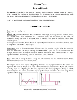
Analog Output (PWM) evive s analog output is in the form of a digital signal that is just very fast, and by very fast we mean VERY fast. A digital output can take either of the two values: HIGH or LOW. To get analog output, what we can do is switch between the two values, at a VERY fast rate; this rate is known as frequency. Frequency is the number of times the switching between HIGH and LOW takes place in 1 second. If we switch the signal between these two values, say, 500 times in 1 second, the output will appear to be continuous; it will appear as if it is an analog signal. 3
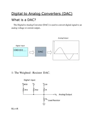
Analog Output (PWM) We are generating analog voltage output using digital pins which are special. They are known as PWM pins, which is the short form of Pulse Width Modulation. 4
Analog Output (PWM) If for this whole time, the voltage is LOW, then the output voltage is 0V and if the voltage is HIGH, the output voltage is 5V. What happens when for some time the pin is HIGH and for some time is LOW. Then accordingly, it generates an average voltage. 5
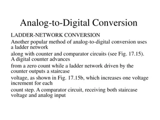
Equation Average voltage = (Time for which signal is HIGH * Value of HIGH + Time for which signal is LOW * Value of LOW)/Total Time Average voltage = (Time for which signal is HIGH * Value of HIGH)/Total Time 6
Equation Average voltage = (Time for which signal is HIGH * Value of HIGH)/Total Time If the voltage is HIGH for 0.5 ms and LOW for 1.5 ms, then the average voltage output is 1.25V. 7
Set PWM pin () output as () The process of obtaining0V to 5V from 0 to 255 is calledscaling. If you want 0 V give 0 PWM If you want 1V give 51 PWM If you want 2.5V give 128 PWM If you want 4V give 204 PWM If you want 5V give 255 PWM 9
Activity: Controlling the Brightness of a LED 10
Interfacing evive with PictoBlox Connect evive to your laptop/PC and open PictoBlox. In PictoBlox, go to the menu and click on the Boards Select the evive. 11
Interfacing evive with PictoBlox Once you ve selected the board, click on the Connect tab and connect the board. 12
Upload Firmware You have to upload the firmware into the device before interacting with it. Click on Upload Firmware button. Once you successfully uploaded the firmware you will see evive logo on evive display. 13
Testing the Block Drag and drop the set PWM block and change the brightness of the LED connected to pin 13. 14
Controlling the brightness of LED Make a variable named Brightness & make the following script. 15
Controlling the brightness of LED On the stage click on variable to get the slider. Now change the value of brightness. 16


")
")
")


 output as ()")