Analysis of Passive Components in Integrated Circuits and Polysilicon Resistors
Explore the significance of passive components like resistors, capacitors, and inductors in integrated circuits. Learn about the quality parameters, layouts, and characteristics of integrated resistors, along with the intricacies of polysilicon resistors for microelectronic system design.

Uploaded on | 3 Views
Download Presentation

Please find below an Image/Link to download the presentation.
The content on the website is provided AS IS for your information and personal use only. It may not be sold, licensed, or shared on other websites without obtaining consent from the author. If you encounter any issues during the download, it is possible that the publisher has removed the file from their server.
You are allowed to download the files provided on this website for personal or commercial use, subject to the condition that they are used lawfully. All files are the property of their respective owners.
The content on the website is provided AS IS for your information and personal use only. It may not be sold, licensed, or shared on other websites without obtaining consent from the author.
E N D
Presentation Transcript
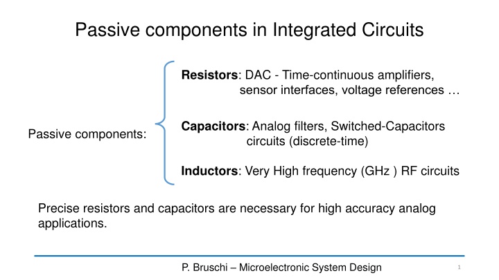
Passive components in Integrated Circuits Resistors: DAC - Time-continuous amplifiers, sensor interfaces, voltage references Capacitors: Analog filters, Switched-Capacitors circuits (discrete-time) Passive components: Inductors: Very High frequency (GHz ) RF circuits Precise resistors and capacitors are necessary for high accuracy analog applications. P. Bruschi Microelectronic System Design 1
Integrated resistors: general layout W L L W = = = + 2 R R with R R R R S S tot C t P. Bruschi Microelectronic System Design 2
Resistor layout for W>>Wmin In some cases, we need to draw a resistor body with a width much larger than the minimum value dictated by the technology. This may occur when we need a resistor of low value that must carry relatively large currents. In this case, the resistor body width is already as large as to allow correct surround of contacts. If there is enough space, we add as many as possible contacts along the resistor width. P. Bruschi Microelectronic System Design 3
Resistors: quality parameters Sheet resistance (RS): Large RSmeans that large resistance values can be obtained using less area Voltage dependence: In integrated resistors, the resistance often depends on the voltage applied to the terminals = + + 2 ( ) 0 ( R )[ 1 ] R V V V 1 2 V V Temperature dependence: ( ) ( ) ] 2 = + + ( ) ( )[ 1 R T R T T T T T 0 1 0 2 0 1 dR R dT = = TCR: temperature coefficient of resistance: TCR 1 P. Bruschi Microelectronic System Design 4
Integrated resistors: Parasitic Components Unavoidable parasitics Needs Care! P. Bruschi Microelectronic System Design 5
Polysilicon resistors P. Bruschi Microelectronic System Design 6
Typical characteristics of polysilicon resistors ResistorType Sheet resistance 30-150 TCR Non (aV1) 50 ppm / V linearity n-plus polysilicon p-plus polysilicon high-res polysilicon Salicided polysilicon 100-500 ppm/ C 50-400 250-1000 ppm/ C -50 ppm / V 400-4000 -1000 ppm/ C, -3000 ppm/ C 100 ppm / V 5-10 2500-3500 ppm/C - P. Bruschi Microelectronic System Design 7
Diffusion Resistors P. Bruschi Microelectronic System Design 8
Voltage dependence in diffused resistors P. Bruschi Microelectronic System Design 9
Properties of diffused resistors ResistorType Sheet resistance 30-80 TCR Non (aV1) 400 ppm / V linearity n-plus on substrate p-plus on n-well 1000-1500 ppm/ C 50-150 1000-1500 ppm/ C 400 ppm / V 400-4000 n-Well on substrate 2000 -3000 ppm/ C 3000 ppm / V P. Bruschi Microelectronic System Design 10
Integrated capacitors: quality parameters Capacitance per unit area: critical when large capacitors have to be integrated into the chip. Typical values : 1 fF/ m2to 8 fF/ m2. Linearity: A linear capacitance should be voltage independent. In some cases, the fact that a capacitance depends on voltage can be exploited to obtain tunable resonant circuits. Temperature dependence. Integrated capacitors exhibit a very low temperature dependence (a few tens of ppm/ C. Thus, this is seldom a critical point. Parasitic components: as for resistors, capacitors may be affected by parasitic components, typically capacitances to the substrate and parasitic diodes, when insulation is obtained by means of reverse- biased junctions. P. Bruschi Microelectronic System Design 11
Integrated Capacitors: MIM capacitors Typical capacitance density: 1fF/ m2 33 m = 1 pF 33 m Need additional process steps Relatively low density Possible leakage Withstand low voltages ( a few V) P. Bruschi Microelectronic System Design 12
Integrated capacitors: MOM capacitors Single layer MOM capacitor Layout of a 6-finger Single-layer MOM Standard metal interconnection layer P. Bruschi Microelectronic System Design 13
Multi-layer MOM capacitors Multi-layer MOMs are required to obtain capacitance density comparable with MIMs + No additional process steps are required to fabricate MOMs + They withstand relatively high voltages (tens of V or more) - Multi-layer MOMs are "walls" that cannot be crossed by other interconnection layers Standard metal layers Vias P. Bruschi Microelectronic System Design 14
Poly-Poly Capacitors Poly-poly capacitors can be integrated only when two polysilicon layers are available + Maximum capacitance density among integrated capacitors (up to 8 fF/ m2) - Higher non-linearity (voltage dependence) with respect to MIM and MOM cap. - Only low voltages can be safely applied The non-linearity derives from the much greater (and non linear) penetration of the electric field into the polysilicon plates with respect to metal ones. P. Bruschi Microelectronic System Design 15
Poly-implant capacitor C1 C2 sub Some properties as poly-poly capacitors but presence of a parasitic junction between the lower terminal and the substrate. P. Bruschi Microelectronic System Design 16
Junction Capacitors + VC- Due to the strong dependence on voltage, junction capacitances are used only for frequency compensation purposes or as bypass capacitors. The dependence on voltage can be used in RF applications to implement varactors for tuning of LC resonators. P. Bruschi Microelectronic System Design 17
Properties of Integrated Capacitors CapacitorType Capacitance per unit area 1 fF / m2 Linearity dependence) < 100 ppm/ V (voltage Parasitic components MIM Capacitance to substrate (bottom plate only) Capacitance to substrate (both terminals only) Capacitance to substrate (both terminals only) Capacitance to substrate (bottom plate only) Diode to Substrate (bottom plate only) Diode to Substrate (bottom plate). Diode terminals. 0.1 fF / m2 MOM (flux) 1 metal layer MOM (flux) 6 metal layer poly-poly < 100 ppm/ V 1 fF / m2 < 100 ppm/ V 6 fF / m2 100 - 1000 ppm/V 6 fF / m2 poly-diffusion 100 - 1000 ppm/V 1 fF / m2 junction very high (up to 30 % / V) between P. Bruschi Microelectronic System Design 18