Antenna Pattern Decoupling Operation in IEEE 802.11ay Channel Modeling
Explore the impact of antenna patterns on channel modeling in high-frequency environments like IEEE 802.11ay. The presentation from Huawei Technologies delves into the necessity of decoupling antenna patterns for accurate system design within the Quasi-Deterministic approach. Detailed measurement campaigns and examples highlight the crucial role of antenna patterns in channel measurements and system operations.

Download Presentation

Please find below an Image/Link to download the presentation.
The content on the website is provided AS IS for your information and personal use only. It may not be sold, licensed, or shared on other websites without obtaining consent from the author. If you encounter any issues during the download, it is possible that the publisher has removed the file from their server.
You are allowed to download the files provided on this website for personal or commercial use, subject to the condition that they are used lawfully. All files are the property of their respective owners.
The content on the website is provided AS IS for your information and personal use only. It may not be sold, licensed, or shared on other websites without obtaining consent from the author.
E N D
Presentation Transcript
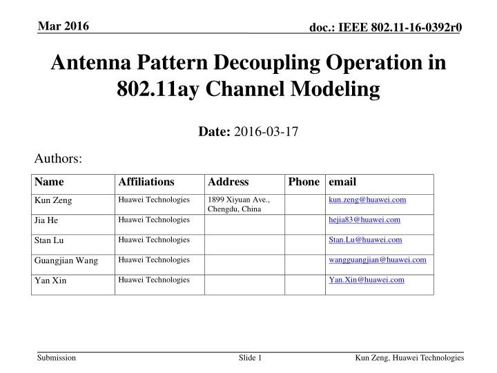
Mar 2016 doc.: IEEE 802.11-16-0392r0 Antenna Pattern Decoupling Operation in 802.11ay Channel Modeling Date: 2016-03-17 Authors: Name Affiliations Address Phone email Huawei Technologies 1899 Xiyuan Ave., Chengdu, China kun.zeng@huawei.com Kun Zeng Huawei Technologies hejia83@huawei.com Jia He Huawei Technologies Stan.Lu@huawei.com Stan Lu Huawei Technologies wangguangjian@huawei.com Guangjian Wang Huawei Technologies Yan.Xin@huawei.com Yan Xin Submission Slide 1 Kun Zeng, Huawei Technologies
Mar 2016 doc.: IEEE 802.11-16-0392r0 Motivation The effects of antenna pattern should be carefully considered in high frequency channel modeling, Measurements in low frequency bands (<6GHz) have used omni-directional/sector antennas, while the same antenna configuration is also applied for operating environment. However, in the higher frequency bands, antenna pattern should be taken into account in system design. If different antenna patterns are applied to channel measurements and system operations, the channel model obtained may not be fully helpful for system design. Quasi-Deterministic (Q-D) approach [1] has been proposed in 802.11ay channel modeling. In this approach, channel models consist of two folds: deterministic components (i.e., D-rays) and random components (i.e., R-/F- rays). D-rays are simulated by ray-tracing method and R-/F- rays are extracted from channel measurements. This presentation addresses the impact of antenna patterns on channel measurement and proposes decoupling the channel modeling from antenna patterns, which we think to be essential in Q-D channel modeling. Submission Slide 2 Kun Zeng, Huawei Technologies
Mar 2016 doc.: IEEE 802.11-16-0392r0 Outline An example of the effects of antenna patterns Antenna pattern decoupling operation in Q-D model Summary Submission Slide 3 Kun Zeng, Huawei Technologies
Mar 2016 doc.: IEEE 802.11-16-0392r0 An Example of the Effects of Antenna Patterns Submission Slide 4 Kun Zeng, Huawei Technologies
Mar 2016 doc.: IEEE 802.11-16-0392r0 Measurement Campaign for Indoor Scenario @73GHz* Wall Tx LOS 0.7m 6m 2m Tx NLOS Cabin 15.4m 12.4m Glass Wall Cabin RX Cabin Picture (Open office at U2 building of Chengdu Huawei Research Center) Floor plan * Here the results@73GHz is presented as a reference to illustrate the effects of antenna pattern in channel measurement. Submission Slide 5 Kun Zeng, Huawei Technologies
Mar 2016 doc.: IEEE 802.11-16-0392r0 Measurement Campaign for Indoor Scenario @73GHz (2) LOS and NLOS are both considered. Main measurement parameters Tx height (m) 2.16 Rx elevation sweep N/A Central frequency (GHz) Rx height (m) 1.8 73 Tx azimuth (deg) 0 Bandwidth (GHz) 1 Tx elevation (deg) 0 Freq. sweep points 1001 Tx location Static Tx antenna Waveguide/ 10dBi Rx antenna Horn/ 20dBi, 25dBi, 30dBi Rx location Static Polarization Vertical Rx azimuth sweep (deg) 0~359 LOS 15.4 Measurement antenna patterns Tx-Rx distance (m) Rx azimuth sweep step (deg) 1 NLOS 12.4 Submission Slide 6 Kun Zeng, Huawei Technologies
Mar 2016 doc.: IEEE 802.11-16-0392r0 Power Angular Spectrum (PAS) LOS LOS NLOS NLOS -25 -55 20dBi 25dBi 30dBi 20dBi 25dBi 30dBi Lobe 1 Lobe 1 -30 Lobe 3 -60 -35 Lobe 2 -65 -40 Lobe 2 Lobe 3 Power (dB) Power (dB) -70 -45 -50 -75 -55 -80 -60 -85 -65 -70 -90 0 50 100 150 200 250 300 350 400 0 50 100 150 200 250 300 350 400 Azimuth angle (deg) Azimuth angle (deg) Observations: Three lobes are presented; For different antenna patterns, the measured PAS are different; Submission Slide 7 Kun Zeng, Huawei Technologies
Mar 2016 doc.: IEEE 802.11-16-0392r0 Angular Spread (AS) AS are estimated from the measured PAS and based on the extraction procedure presented in WINNER II channel models [2]. AS (deg) Cases Rx antennas Lobe 1 Lobe 2 Lobe 3 Global 30dBi 2.9 2.7 4.5 26.2 LOS 25dBi 5.6 5.5 7.0 34.9 20dBi 5.6 6.0 14.3 40.9 30dBi 3.2 3.2 5.7 46.3 NLOS 25dBi 9.7 6.6 5.7 50.4 20dBi 11.6 6.7 5.7 41.8 From the table, it is observed that the values of AS with different Rx antenna patterns are different. It implies a necessity that the effect of antenna patterns on the extracted parameters for channel modeling be removed. Submission Slide 8 Kun Zeng, Huawei Technologies
Mar 2016 doc.: IEEE 802.11-16-0392r0 Antenna Pattern Decoupling Operation in Q-D Channel Modeling Submission Slide 9 Kun Zeng, Huawei Technologies
Mar 2016 Relationship between Ideal and Measured Channel In general, the relationship between ideal (pure propagation) channel and measured channel can be expressed as doc.: IEEE 802.11-16-0392r0 ( ) = , , , , h h t Ideal channel, eq.(3.1) in [1] tx tx rx rx ( ) ( ) , L M ( ) ( tx ) ( ) l tx ( ) m tx , l m tx , l m j p e Measured channel tx tx = , 1 l m Tx antenna pattern ( ) ( ) , L M ( rx ) ( rx ) ( ) l rx ( ) m rx , l m , l m j p e rx rx = , 1 l m Rx antenna pattern Measured_Channel = Ideal_Channel Antenna_Pattern -- convolution operation; L, M -- the antenna pattern resolution in the azimuth and elevation plane, respectively; p , -- the amplitude and phase of the (l, m)antenna pattern resolution unit, respectively. Submission Slide 10 Kun Zeng, Huawei Technologies
Mar 2016 Relationship between Ideal and Measured Channel (2) doc.: IEEE 802.11-16-0392r0 In Q-D approach, the channel model consists of two parts, Channel = Deterministic_channel_components + Random_channel_components where Deterministic_channel_components are simulated by ray-tracing; Random_channel_components are obtained from channel measurements; Antenna pattern can be set to the isotropic configuration in ray-tracing. Therefore, the effects of antenna pattern mainly occur in random components modeling in Q-D. Submission Slide 11 Kun Zeng, Huawei Technologies
Mar 2016 doc.: IEEE 802.11-16-0392r0 Antenna Pattern Decoupling Basically, antenna pattern decoupling can be defined as the operation of decoupling the channel model from the measurement antenna patterns, which can be expressed as Ideal_Channel = Measured_Channel Antenna_Pattern Measured PAS Measured PAS Power Power Antenna Pattern Decoupling 25 Antenna pattern info. 20 15 10 1 2 3 4 5 6 7 Antenna pattern-independent channel/Angular distribution in the actual channel 5 0 -5 -10 -15 -20 -25 -200 -150 -100 -50 0 50 100 150 200 Submission Slide 12 Kun Zeng, Huawei Technologies
Mar 2016 doc.: IEEE 802.11-16-0392r0 How to Generate the Simulation Channel Since the channel model is ideal and should be independent of antenna patterns, in simulations, the effect of antenna patterns should be compensated/reconstructed. Simulation_Channel = (Deterministic_channel_components + Random_channel_components ) Antenna_Pattern Submission Slide 13 Kun Zeng, Huawei Technologies
Mar 2016 Procedure of Antenna Pattern Decoupling Operation doc.: IEEE 802.11-16-0392r0 The general procedure of antenna pattern decoupling should include the following steps: Step 1: estimate the path of propagation (angular domain/delay domain/both); Antenna Decoupling Step 2: remove the measurement antenna pattern**; Step 3: reconstruct/compensate the extracted data with measured/new antenna pattern; Application/ Verification Step 4 (optional): evaluate the effect of reconstruction and antenna decoupling ** There are couples of methods to achieve Step 2, such as MUSIC[Schmidt], CLEAN[Clarke] or SAGE[Fessler] algorithm in the field of signal processing, and so on. This step can be treated as an inverse problem. Submission Slide 14 Kun Zeng, Huawei Technologies
Mar 2016 doc.: IEEE 802.11-16-0392r0 General Criterion for Antenna Pattern Decoupling To guarantee the performance of antenna pattern decoupling operation, we suggest the following criterion to evaluate the effectiveness of specific decoupling algorithm. Min Reconstructed_Channel Orignal_Measured_Channel 2 MSE Minimum Squared Error Submission Slide 15 Kun Zeng, Huawei Technologies
Mar 2016 doc.: IEEE 802.11-16-0392r0 Summary The effect of antenna patterns should be considered in 802.11ay channel modeling. This effect mainly affects the random components modeling in the Q- D channel modeling method. In this presentation, we propose considering antenna pattern decoupling operations as an essential processing step in Q-D channel modeling. In addition, we propose a general criterion to evaluate the effectiveness of antenna pattern decoupling. Submission Slide 16 Kun Zeng, Huawei Technologies
Mar 2016 doc.: IEEE 802.11-16-0392r0 References [1] IEEE 802.11-15/1150r2, Channel Models for IEEE 802.11ay [2] IST-4-027756 WINNER II D1.1.2 v1.0, WINNER II Channel Models, Part II- Radio Channel Measurement and Analysis Results Submission Slide 17 Kun Zeng, Huawei Technologies
Mar 2016 Backup: Preliminary Results for Antenna Pattern Decoupling Operation (LOS case) doc.: IEEE 802.11-16-0392r0 Original PAS before antenna pattern decoupling Extracted Angular distribution after antenna pattern decoupling Submission Slide 18 Kun Zeng, Huawei Technologies
Mar 2016 Backup: Preliminary Results for Antenna Pattern Decoupling Operation (LOS case) doc.: IEEE 802.11-16-0392r0 Reconstructed PAS (black: original ; red: reconstructed) Cases Rx antennas Deviation btw O&R (dB) 30dBi 0.1 LOS 25dBi 0.1 20dBi 0.1 Submission Slide 19 Kun Zeng, Huawei Technologies
Mar 2016 Backup: Preliminary Results for Antenna Pattern Decoupling Operation (NLOS case) doc.: IEEE 802.11-16-0392r0 Original PAS before antenna pattern decoupling Extracted Angular distribution after antenna pattern decoupling Submission Slide 20 Kun Zeng, Huawei Technologies
Mar 2016 Backup: Preliminary Results for Antenna Pattern Decoupling Operation (NLOS case) doc.: IEEE 802.11-16-0392r0 Reconstructed PAS (black: original ; red: reconstructed) Cases Rx antennas Deviation btw O&R (dB) 30dBi 0.5 LOS 25dBi 0.5 20dBi 0.3 Submission Slide 21 Kun Zeng, Huawei Technologies
Mar 2016 doc.: IEEE 802.11-16-0392r0 Straw Poll 1 Would you agree that 11ay channel modeling shall incorporate antenna pattern independent methodology? Y-N-A: Submission Slide 22 Kun Zeng, Huawei Technologies