Explore the intricacies of wire antennas in the field of antenna theory and design. Learn about different configurations such as dipoles, helix, and loops, and delve into concepts like small dipole antennas and thin linear antennas. Gain insights into the magnetic and electric fields, power flow, radiation resistance, and more.
Please find below an Image/Link to download the presentation.
The content on the website is provided AS IS for your information and personal use only. It may not be sold, licensed, or shared on other websites without obtaining consent from the author. If you encounter any issues during the download, it is possible that the publisher has removed the file from their server.
You are allowed to download the files provided on this website for personal or commercial use, subject to the condition that they are used lawfully. All files are the property of their respective owners.
The content on the website is provided AS IS for your information and personal use only. It may not be sold, licensed, or shared on other websites without obtaining consent from the author.
E N D
Presentation Transcript
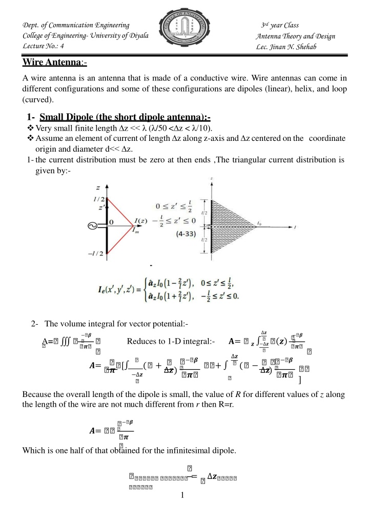
Dept. of Communication Engineering College of Engineering-University of Diyala Lecture No.: 4 3rd year Class Antenna Theory and Design Lec. Jinan N. Shehab WireAntenna:- A wire antenna is an antenna that is made of a conductive wire. Wire antennas can come in different configurations and some of these configurations are dipoles (linear), helix, and loop (curved). 1- Small Dipole (the short dipole antenna):- Very small finite length z << ( /50 < z < /10). Assume an element ofcurrentoflength z alongz-axis and zcentered on the coordinate origin and diameter d<< z. 1-the current distribution must be zero at then ends ,The triangular current distribution is given by:- 2- The volume integral for vector potential:- ? ? ? ? (?) A= Reduces to 1-D integral:- ?= ? ? ? ? ? ? ? ? ?= ? [ ( + ?) + ( ?) ] ? Because the overall length of the dipole is small, the value of R for different values of z along the length of the wire are not much different from r then R=r. ? ? ?= Which is one half of that obtained for the infinitesimal dipole. = ? 1
Dept. of Communication Engineering College of Engineering-University of Diyala Lecture No.: 4 3rd year Class Antenna Theory and Design Lec. Jinan N. Shehab 3-The magnetic field (H) expration:- ? ? ?? ? = ? ?[ + ? ] 4-The electric field (E)expration:- ? ? ? ? ? ?? ? ?+ ? [ ? ] ?= ? [ + ? +( ? ) ] For far_field ( r >>1), the above equation reduce to:- = ? ? ? ? ? ??= ? ?? ? & ? ? 5-The power flowing density (s):- ? ? = ( ? ) = ? ( ) ? 6-The total power flowing out through a sphere (prad):- ? ?( ) ? = . = Note:- from abovewe found the total radiation poweris reduced by factorof 4 from that of the ideal dipole:- = 7- The radiation resistance (Rrad):- ? ? ? ? ( ) = ?( ) = | | Then, the radiation resistance for small dipole is reduced by factor of 4 from that of the ideal dipole:- = = Thin linear antenna:- 2- The far field patterns of thin linear antenna will be developed.Assuming that:- Thinantennameans itsdiameterissmallcomparedtoitswavelength,(diameterd< /100) Antenna is fed at the center by a balanced two wire transmission line and Sinusoidal current distributionalong variouslengthofline ( examples of theapproximatenatural-current 2
Dept. of Communication Engineering College of Engineering-University of Diyala Lecture No.: 4 3rd year Class Antenna Theory and Design Lec. Jinan N. Shehab distributions on a number of thin, linear, center-fed antennas of different length are as shown in figure:- Figure Approximate natural current distribution for thin linear center fed antenna of various length. If we assume that the dipole antenna is driven at its center, we may:- 1-assume that the current distribution is symmetrical along the antenna:- (? ) = ?? [?( |? |)] ? ?? [?( + ? )] ? |? | |? | (?) = { ?? [?( ?)] ? |?| 2-We use thepreviouslydefined approximations for the far field magnetic vectorpotentialto determine the far fields of the center-fed dipole:- ? ( ) ? ? (? ) ?? ? ? substituting the sinusoidal current expression I(z )from eq.in step (1)into eq.in step (2) given: ?( ) = & ??= ? ? ? ? ?? ? ?? ? ?] ??= [ ?? [?( + ?)] ?+ ?? [?( ?)] ? ? . 3
Dept. of Communication Engineering College of Engineering-University of Diyala Lecture No.: 4 3rd year Class Antenna Theory and Design Lec. Jinan N. Shehab ?? ( + ) = [ ?? ( + ) ? ?( + )] + = ? ?; = ?; = + ? Evaluating these integrals givesAz (Center-fed dipole far field magnetic vector potential):- ? ? ? ?[( ) ? ??] ? ?( ) ? ? ? ??= ? 3-The far field electric field can be found from far fields of the center-fed dipole in terms of the magnetic vector potential are:- ? ? ? ?[( ) ? ??] ? ?( ) ? ? ? ? ??= ??& ?= ? ?? ? ? = , : ? ?[( ) ? ??] ? ?( ) ?? ? ? ? ? ? ? ?[( ) ? ??] ? ?( ) ?? ? ? ??= ? For ?=?, ? ? : ??= [ ] 2 ? ? ?[( ) ? ??] ??= [ ] ?? ? For L= , full- wave dipole:- ? ?[(?)? ??] ??= [ ] ?? ? For ?=3?, ? : 2 ? ? ?[( ) ? ??] between ??= relationship [ ] ?? ? the 4- By using the established ?? ? : ? ? ?[( ) ? ??] ? ?( ) ??= ? [ ] = ??= ? ?? ? 5- The time-average complex Poynting vector in the far field of the center-fed dipole is:- 4
Dept. of Communication Engineering College of Engineering-University of Diyala Lecture No.: 4 3rd year Class Antenna Theory and Design Lec. Jinan N. Shehab ? ? ? ? cos[(2) cos?] cos(2) sin? cos[(2) cos?] cos(2) sin? 1 60 ]} {2? [ ? ]} = ?2{ [ ? ? ?[( ) ? ??] ? ?( ) ?? ? ] = ? [ 6-The total power flowing out through a sphere of radius R surrounding a small dipole is:- ? ? ?[( ) ? ??] ? ?( ) ?? ? ? ] .( ?? ?) ? = . = ? [ ?(? ?[( ) ? ??] ? ?( )) ?? ? ? ? ? = ?(? ?[(? ) ? ??] ? ?(? ) ?? ? ) = For L= /2 , ? ?(? ?[( ) ? ??] ? ??) ?? ? = = . 7- The radiation resistance for L= /2 is:- = | | = . 8- The terminal impedance also include some inductive reactance in series with ?? , then the input impedance of an infinitely thin /2 long dipole is :- = + ? = + . ? 3 Monopole antenna:- a. Image theory:- To analyze the performance of an antenna near an infinite plane conductor, virtual sources (images) will be introduced to account for the reflections.As the name implies, these are not real sources but imaginary ones, which when combined with the real sources, form an equivalent system. b. Monopole antenna:- Basically,thequarter-wavemonopoleantennaconsistsofone-halfofahalf-wavedipole antenna located on a conducting ground plane as in Figure. The monopole antenna is perpendicular to the plane, which is usually assumed to be infinite and perfectly conducting. It is fed by a coaxial cable connected to its base Using image theory, the monopole antenna over a PEC ground plane may be shown to be equivalent to a dipole antenna in a homogeneous region. The quarter-wavelength vertical antenna, also called a Marconi antenna is widely used. = ? = / 5
Dept. of Communication Engineering College of Engineering-University of Diyala Lecture No.: 4 3rd year Class Antenna Theory and Design Lec. Jinan N. Shehab The monopole uses the earth to act as a type of electrical mirror, effectively providing the other quarter wavelength making it electrically equivalent to a vertical dipole. 1- The input impedance of the equivalent antennas is given by:- ? ? = = 2 ? ( ? ) ? = 2 ? ? ? The input impedance of the monopole is exactly one-half that of the equivalent dipole. Therefore, we may determine the monopole radiation resistance for monopoles of different lengths according to the results of the equivalent dipole. 6
Dept. of Communication Engineering College of Engineering-University of Diyala Lecture No.: 4 3rd year Class Antenna Theory and Design Lec. Jinan N. Shehab 2- The power radiated is only half that of a dipole with the same current:- ? ? = = = | | | | 3- The total power radiated by the monopole is one-half that of the equivalent dipole. But, the monopole radiates into one-half the volume of the dipole yielding equivalent fields and power densities in the upper half space. 7
Dept. of Communication Engineering College of Engineering-University of Diyala Lecture No.: 4 3rd year Class Antenna Theory and Design Lec. Jinan N. Shehab 4 Small loop antenna:- Loop antennas have the same desirable characteristics as dipoles and monopoles in that they are inexpensive and simple to construct:- Small loop antenna are frequently employed as receiving antennas at low frequencies and it is also worthwhile to be take up its analysis. The loop is coinciding with z=0 plane with its center at the origin. The currents in its r.m.s will be directed either in x or y direction. Loop antennas come in a variety of shapes (circular, rectangular, elliptical, etc.) The far fields of an electricallysmall loop antennaare dependenton the loop area but are independent of the loop shape. 8
Dept. of Communication Engineering College of Engineering-University of Diyala Lecture No.: 4 3rd year Class Antenna Theory and Design Lec. Jinan N. Shehab Very important note. The square loop, located in the x-y plane and centered at the coordinate origin, the components of vector potential ? = ? + ? . The square loop may be viewed as four segments which each represent an infinitesimal dipole carrying current in a different direction. In the far field, the distance vectors from the centers of the four segments become almost parallel. As always in far field expressions, the above approximations are used in the phase terms of the magnetic vector potential, but we may assume that R1 R2 R3 R4 r for the magnitude terms. The far field magnetic vector potential of a z-directed infinitesimal dipole centered at the origin is:- Where K=? The individual far field magnetic vector potential contributions due to the four segments of the current loop are:- Combining the x-directed and y-directed terms yields:- 9
Dept. of Communication Engineering College of Engineering-University of Diyala Lecture No.: 4 3rd year Class Antenna Theory and Design Lec. Jinan N. Shehab Which gives:- The overall vector potential becomes:- The power radiation:- ? = ( ) The radiation resistance:- = = ( ) = ( ) and for n-loop = ( ) 10