ANTILOCK BRAKING SYSTEM
The Anti-lock Braking System (ABS) is a crucial safety feature in automobiles that prevents wheels from locking up during braking, ensuring better control and shorter stopping distances. This project outlines the objectives, components, working principles, and benefits of ABS, focusing on stability and steerability enhancement in vehicles.

Download Presentation

Please find below an Image/Link to download the presentation.
The content on the website is provided AS IS for your information and personal use only. It may not be sold, licensed, or shared on other websites without obtaining consent from the author.If you encounter any issues during the download, it is possible that the publisher has removed the file from their server.
You are allowed to download the files provided on this website for personal or commercial use, subject to the condition that they are used lawfully. All files are the property of their respective owners.
The content on the website is provided AS IS for your information and personal use only. It may not be sold, licensed, or shared on other websites without obtaining consent from the author.
E N D
Presentation Transcript
Vehicle Dynamics (ME5670) ANTILOCK BRAKING SYSTEM MODELING AND DEVELPOMENT Siva Teja Golla (ME14MTECH11025) Harshad Keskar (ME14MTECH11027) Mohini Kale (ME14MTECH11029) Nikhil Mhaske (ME14MTECH11030) Sukanya Joshi (ME14MTECH11037) Indian Institute of Technology, Hyderabad ANTILOCK BRAKING SYSTEM 1
INTRODUCTION Anti-lock braking system (ABS) is an automobile safety system that allows the wheels on a motor vehicle to maintain tractive contact with the road surface according to driver inputs while braking, preventing the wheels from locking up and avoiding uncontrolled skidding. ABS generally offers improved vehicle control and decreases stopping distances on dry and slippery surfaces. ABS modulates the brake line pressure independent of the pedal force, to bring the wheel speed back to the slip level range that is necessary for optimal braking performance. ANTILOCK BRAKING SYSTEM 2
PROJECT OUTLINE Objectives of ABS Components of ABS Working of ABS Mathematical model System model Results Conclusion References ANTILOCK BRAKING SYSTEM 3
OBJECTIVES OF ABS To reduce stopping distance 1. The road surface type and conditions can be inferred from the vehicle's braking pressure, wheel slip measurements, and deceleration rate comparisons. 2. The wheel slip is regulated so that the road adhesion coefficient is maximized. By keeping all of the wheels of a vehicle near the maximum friction coefficient, an antilock system can attain maximum fictional force 3. In turn, this strategy leads to the minimization of the vehicle stopping distance. ANTILOCK BRAKING SYSTEM 4
Stability 1. A locked-up wheel generates a reduced braking force, smaller than the peak value of the available adhesion between tires and road. A locked-up wheel will also lose its capability to sustain any lateral force. This may result in the loss of vehicle stability. 2. The basic purpose of a conventional ABS system is thus to prevent any wheel from locking and to keep the longitudinal slip in an operational range by cycling the braking pressure. ANTILOCK BRAKING SYSTEM 5
Steerability 1. Good peak frictional force control is necessary in order to achieve satisfactory lateral forces and, therefore, satisfactory steer-ability. 2. If an obstacle appears without warning, emergency braking may not be sufficient. When the wheels are locked, car no longer respond to the driver s steering intention. 3. With ABS car remains steerable even during emergency braking, and thus the obstacle can be safely avoided. ANTILOCK BRAKING SYSTEM 6
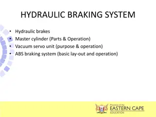
COMPONENTS OF ABS The primary components of the ABS braking system are: Electronic control unit (ECU) 1. It receives signals from the sensors in the circuit and controls the brake pressure at the road wheels according to the data analysed by the Unit. 2. ECU assists the vehicle operator to prevent wheel lockup by regulating the wheel slip. Hydraulic control unit or modulator 1. It receives operating signals from the ECU to apply or release the brakes under ABS conditions. 2. It executes the commands using three solenoid valves connected in series with the master cylinder and the brake circuits- one valve for each front wheel hydraulic circuit, and one for both of the rear wheels. Thus brakes can be actuated by controlling hydraulic pressure. ANTILOCK BRAKING SYSTEM 7
Power booster and master cylinder assembly 1. It is activated when the driver pushes down on the brake pedal. The master cylinder transforms the applied pedal force into hydraulic pressure which is transmitted simultaneously to all four wheels. 2. It provides the power assistance required during braking. Wheel sensor unit 1. Speed sensors are comprised of a magnet wrapped in a coil and a toothed sensor ring. An electrical field given off by the contact between the magnet and the toothed ring creates a AC voltage. 2. The voltage frequency is directly proportional to the wheel's rotational speed. 3. It monitors the rotational speed of the wheel and transmits this data to the ABS control module. ANTILOCK BRAKING SYSTEM 8
WORKING OF ABS If a wheel-speed sensor signals a lock up - the ECU sends a current to the hydraulic unit. This energizes the solenoid valve. The action of the valve isolates the brake circuit from the master cylinder. This stops the braking pressure at that wheel from rising, and keeps it constant. It allows wheel velocity to increase and slip to decrease. When the velocity increases, ECU re-applies the brake pressure to restrict the wheel slip to a particular value. Hydraulic control unit controls the brake pressure in each wheel cylinder based on the inputs from the system sensor. This in result controls the wheel speed. ANTILOCK BRAKING SYSTEM 9
MATHEMATICAL MODEL Wheel slip: When the braking action is initiated, a slippage between the tire and the contacted road surface will occur, which make the speed of the vehicle to be different from that of the tire. The longitudinal slip is defined as ? =????? ??? ????? The side slip angle is ? = ??? 1??? ?? Force and velocity components on tyre ANTILOCK BRAKING SYSTEM 10
Vehicle Dynamics According to Newton's second law, the equation of motion of the simplified vehicle can be expressed by, ?? ? = ?? ?? The road friction force is given by Coulomb law ??= ?? The total mass of the quarter vehicle can be written as ??= ?????+?? Thus, the total normal load cm be expressed by ? = ??? ?? ?? is the longitudinal weight transfer load due to braking 4 ANTILOCK BRAKING SYSTEM 11
Simulink model for vehicle dynamics ANTILOCK BRAKING SYSTEM 12
Wheel dynamics According to Newton's second law, the equation of motion at wheel level for the rotational DOF is given by, ?? ? = ??+ ???? ANTILOCK BRAKING SYSTEM 13
Simulink model for wheel dynamics ANTILOCK BRAKING SYSTEM 14
SYSTEM MODEL Assumption: Only a linear model was considered and does not include actual road conditions. The system here is modelled only for straight line braking. ANTILOCK BRAKING SYSTEM 15
INPUT PARAMETERS FOR SIMULINK MODEL ? = 32.18 ??/?2 ?0= 88 ??/? ?? = 1.25 ?? ? = 50 lbs ?????= 1500 ??? ?? ?? = 0.01 ? ??= 5 ??4 Gravitational constant Initial velocity of vehicle Wheel Radius Mass of vehicle Maximum Braking Torque Hydraulic Lag Moment of Inertia ANTILOCK BRAKING SYSTEM 16
RESULTS ANTILOCK BRAKING SYSTEM 17
VEHICLE SPEED AND WHEEL SPEED (WITHOUT ABS) ANTILOCK BRAKING SYSTEM 18
VEHICLE SPEED AND WHEEL SPEED (WITH ABS) ANTILOCK BRAKING SYSTEM 19
SLIP (WITHOUT ABS) ANTILOCK BRAKING SYSTEM 20
SLIP (WITH ABS) ANTILOCK BRAKING SYSTEM 21
STOPPING DISTANCE (WITHOUT ABS) ANTILOCK BRAKING SYSTEM 22
STOPPING DISTANCE (WITH ABS) ANTILOCK BRAKING SYSTEM 23
CONCLUSION It is inferred that ABS improves the braking performance. The stopping distance after using ABS system has considerably reduced. The error in slip and desired slip is used to manipulate brake pressure in brake cylinder. ANTILOCK BRAKING SYSTEM 24
REFERENCES Tianku Fu, Modelling and performance analysis of ABS system with non-linear control , 2000. Tobias Eriksson, Co-simulation of full vehicle model in Adams and anti-lock brake system model in Simulink , 2014. ANTILOCK BRAKING SYSTEM 25
THANK YOU! ANTILOCK BRAKING SYSTEM 26
")


")
")
")
")