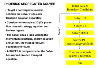
APD Simulations Using Silvaco: Analytical Doping Profiles and Impact Ionization Tuning
In this insightful study, APD simulations using Silvaco software are detailed, including the utilization of analytical doping profiles and tuning of the impact ionization model parameters. The investigation covers the use of the Error Function for doping profiles, the impact-ionization model with Selberher parameters, and the electric field variation inside the APD structure. The results showcase the importance of parameter tuning for accurate simulation outcomes and shed light on potential improvements for optimizing device performance.

Download Presentation

Please find below an Image/Link to download the presentation.
The content on the website is provided AS IS for your information and personal use only. It may not be sold, licensed, or shared on other websites without obtaining consent from the author.If you encounter any issues during the download, it is possible that the publisher has removed the file from their server.
You are allowed to download the files provided on this website for personal or commercial use, subject to the condition that they are used lawfully. All files are the property of their respective owners.
The content on the website is provided AS IS for your information and personal use only. It may not be sold, licensed, or shared on other websites without obtaining consent from the author.
E N D
Presentation Transcript
APD simulations using Silvaco Ranjeet Dalal (Delhi Uni.) 13-1-2016 Meeting 1
APD simulations using Silvaco at Delhi Bulk =1.47e14cm-3 Device thickness = 130 m - Various analytical doping profiles available in Silvaco were used - Doping profile using Error Function (Dist.) is very near to actual doping profile - Error Function (Dist.) is used for all other simulations for 130 m APD with junction depth of 56.9 m (assuming that 100 m front is removed as described in paper) and later with 36.9 m 2
Tuning of Impact-Ionization model Default parameters No hole multiplications -Silvaco and Synopsis uses Selberher model for Impact ionization - Impact Ionization coefficients for holes and electrons are comparable (though somewhat lower values of coefficient for holes than that of electron) - If default Selberher parameters are used, continuous avalanche are produced at higher biases. - Such a pulse at 1600V (above left) is shown for silvaco and similar result was seen for the Synopsis -After switching off the hole multiplication, TCT pulse looks similar to measurements. - Hence, hole multiplication is switched-off for rest of the simulations 3
Infrared-Front TCT for Junction 56.9 m TCT signals are amplified with bias 4
Gain for Infrared-Front (Junction 56.9 m) Gain curve for Infrared laser -Gain at a given bias is defined with respected to integrated signal of the same bias with no no impact ionization. For example, integrated charge with impact ionization at 1700V is about 407 times higher that integrated charge without any charge multiplication case - Plot is very much similar to plot number 7 of APD paper by Mickel et al. 5
E field variation inside APD str. - Electric field plots shows that depletion have not reached to the front side - No signal obtained for 480 nm laser (with 0.1 micron as penetration depth) even at 1600V - This has been confirmed by running actual simulations too (results not shown here) - Either another 20 microns are to be removed from the front side or will have to reduce the doping of p-side Next Step: Reduced junction depth by 20 micron 6
Simulations with Junction Depth = 36.9m APD thickness - 130 m 7
1060nm Front TCT for junction depth = 36.9m -Fluence = 0 - Temp = 297K 9
1060nm Front TCT for junction depth = 36.9m TCT signal for F = 1e15neqcm-2 - Fluence = 0, Temp = 297K - Fluence 1e15 neqcm-2 , Temp = 253K - Gain is calculated w.r.t. signal without any Impact Ionization (keeping all other parameters same) - Gain is a strong function of bias - Very significant effect of irradiation on APD gain is seen 10
480nm Front TCT for junction depth = 36.9m -Fluence = 0, Temp = 297K - Fluence 1e15 neqcm-2 , Temp = 253K - Slow signal decay for non-irradiated case - Narrow peak after irradiation 11
E field for junction depth = 36.9m -Fluence = 0, Temp = 297K - Fluence 1e15 neqcm-2 , Temp = 253K - Slow signal decay for non-irradiated (480nm) may be due to very low electric field near surface 12
Gain for 480nm Front TCT for junction= 36.9m - Fluence = 0, Temp = 297K - Fluence 1e15 neqcm-2 , Temp = 253K - Gain is calculated w.r.t. signal without any Impact Ionization (keeping all other parameters same) 13
Gain comparison for 480nm and 1060nm laser - Higher gain is expected for 480nm as electrons travel whole of the sensor volume before collection at backside 14
Irradiation effect - Gain is strongly affected by irradiation - Need to see the effect of dopings and junction variation ! 15
Suggestions needed for further work! - Thanks for your attention! 16
Some LGAD news Bulk 3e14 cm-3 P-well doping = 3e16 cm-3 (peak) 7micron depth DU simulation for 50um LGAD CMOS gain, Kramberger, JINST 2015 - LGAD radiation hardness is affected by bulk doping variation - Simulation indicate that the better radiation hardness is expected for higher bulk doping - LGAD Gain can vary with fluence similar to CMOS - Currently involved with thin LGAD and CMOS simulations too. 17
Irradiation effect Radiation damage simulations are carried out using already published and tested two trap model (R. Dalal et al., Vertex-2014) - It was developed during HPK campaign for proton irradiation - It creates correct amount of leakage current, full depletion voltage (or CV), double peak electric field profile and CCE for fluence at least up to 2e15 neqcm-2 No acceptor removal term have been used in these simulations - Simulations are carried out at 253K No. Trap Energy Level gint (cm-1) e (cm-2) h(cm-2) 1. Acceptor Ec-0.51eV 4 2x10-14 3.8x10⁻¹⁵ 2. Donor Ev+0.48eV 3 2x10-15 2x10-15 Parameter table for two trap model used in present simulations 18


")