Arduino Sketch Structure and Language Elements
Learn the basics of writing an Arduino sketch, including the structure, main elements, and examples. Explore variables, setup and loop functions, variable definitions, arithmetic operators, control structures, and more. Get started with Arduino programming today!

Download Presentation

Please find below an Image/Link to download the presentation.
The content on the website is provided AS IS for your information and personal use only. It may not be sold, licensed, or shared on other websites without obtaining consent from the author. If you encounter any issues during the download, it is possible that the publisher has removed the file from their server.
You are allowed to download the files provided on this website for personal or commercial use, subject to the condition that they are used lawfully. All files are the property of their respective owners.
The content on the website is provided AS IS for your information and personal use only. It may not be sold, licensed, or shared on other websites without obtaining consent from the author.
E N D
Presentation Transcript
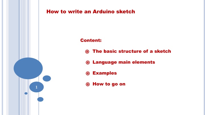
How to write an Arduino sketch Content: The basic structure of a sketch Language main elements Examples How to go on 1
How to write an Arduino sketch The Arduino language is a sort of simplified C Basic hints: Each statement must end with semicolon ; The code is case sensitive Variables cannot use same words as existing commands Comments start with // or are enclosed between /* and */ 2
The minimum amount of elements in a sketch Variable definition void setup() { // put your setup code here, to run once: } void loop() { // put your main code here, to run repeatedly: } setup : It is called only when the setup : It is called only when the Arduino powered on or reset. It is used to initialize powered on or reset. It is used to initialize variables and pin modes. variables and pin modes. Arduino is is 3 loop : The loop functions runs continuously loop : The loop functions runs continuously till the device is powered off. The main logic till the device is powered off. The main logic of the code goes here. of the code goes here.
Variable definition Variables need to be declared before being used. Their names Variables need to be declared before being used. Their names should be different from should be different from Arduino Arduino keywords. Datatype Datatype Property Range Property Range byte 8 bit without decimal point (0, 255) byte 8 bit without decimal point (0, 255) int int 16 bit integer with sign ( 16 bit integer with sign (- -32768 , 32767) long 32 bit integer with sign long 32 bit integer with sign float 32 bit with decimal digits float 32 bit with decimal digits .. Others . .. Others . string string boolean boolean .. .. keywords. 32768 , 32767) 4
Arithmetic and logical operators Variables may be combined through mathematical or logic Variables may be combined through mathematical or logic operators. operators. Basic Arithmetic: Basic Arithmetic: +, +, - -, *, / , *, / Other functions: Other functions: sqrt sqrt(x), abs(x), (x), abs(x), pow Trigonometric: Trigonometric: sin(x), sin(x), cos cos(x), tan(x) x in rad pow( (base,exponent base,exponent) ) (x), tan(x) x in rad Comparison: Comparison: >, <, >=, <=, ==, !=, .. >, <, >=, <=, ==, !=, .. Boolean: Boolean: && (AND), || (OR), ! (NOT) && (AND), || (OR), ! (NOT) Example: int a, b,c; a= 2; b= 3; if(a*b>5) c=100; 5
Control structures Control structures allow to execute different parts of a code Control structures allow to execute different parts of a code depending on the result or to repeat parts of a code under depending on the result or to repeat parts of a code under specified conditions specified conditions if if if else if else do while do while for for { } Example: for(int i=0; i<100; i++) { .. Statements inside the for loop } 6
Define pin mode A pin on A pin on arduino using using pinMode pinMode function. arduino can be set as input or output by can be set as input or output by function. pinMode(13, OUTPUT); // sets pin 13 as output pin pinMode(13, INPUT); // sets pin 13 as input pin 7
Reading/writing digital values A digital input or output may have the following values: A digital input or output may have the following values: 0 (0V) = LOW 0 (0V) = LOW 1 (5V) = HIGH 1 (5V) = HIGH and we can read or write through the commands and we can read or write through the commands digitalRead digitalRead, , digitalWrite digitalWrite digitalWrite(13, LOW); // Sets the output voltage on pin 13 to 0V digitalWrite(13, HIGH); // Sets the output voltage on pin 13 to 5V a = digitalRead(2); // reads the value of pin 2 into the variable a 8
Basic time instructions Commands are executed one after the other, but we can insert a delay in between.. delay(10); // Waits 10 milliseconds delayMicroseconds(400); // Waits 400 microseconds We may have access to the time from the Arduino clock through the commands: a = millis(); // returns the number of milliseconds since the beginning of the program Since the counter is based on a 32 bit register, the max number of milliseconds will be 232 -1 = 4.294.967.295 (about 49.7 days) 9
The first Arduino sketch: blinking the internal LED The Arduino board has a LED already mounted on pin#13. This can be employed for the first basic tests, without any external component. Remember: any external LED must be powered through a resistor, to limit the current and prevent it burns: 5V Usually LED require about 2V and 10-20 mA, so for 5V, we need a resistor of (5-2)/0.01 = 300 Ohm 10 R Ground
The first Arduino sketch: blinking the internal LED // Blink //Turns on the LED for 1 second, then off for 0.5 second, repeatedly int led = 13; void setup() { pinMode(led, OUTPUT); // initialize the digital pin as an output. } void loop() { digitalWrite(led, HIGH); // turn the LED on (HIGH is the voltage level) delay(1000); // wait for a second digitalWrite(led, LOW); // turn the LED off by making the voltage LOW delay(500); // wait for 500 mseconds } 11
What next: Modify the sketch (Exercise 1) Modify the previous sketch (blink.ino) to introduce different light sequences for the LED. Examples: -- Produce short or long light pulses with different delays -- Produce light sequences which transmit a word in the Morse alphabet (for instance an SOS) Letter Sequence A . ------- B,C,D,.. S . . . O --- --- --- 12 -- Check what is the shortest light pulse you can perceive
Controlling sounds with Arduino A basic way of producing a sound with Arduino is to employ a passive buzzer, which can be programmed to play a note (frequency) with its duration. The quality is not very good, (based on piezoelectric effect) but it is very simple. Sophisticated audio control requires additional boards. 13
Controlling sounds with Arduino The buzzer is connected to a digital pin Basic commands: tone(BuzzerPin, f); // Start playing a sound with frequency f noTone(BuzzerPin); // Stop playing delay(delta); // introduces a delay of delta milliseconds Note Frequency Additional semitones Do 131 Do# 139 Re 147 Mib Mi 165 Fa# 185 Fa 175 Lab 208 Sol 196 Sib 233 La 220 Si 247 Next octave: a factor 2 Do 131*2 = 262 .. 156 14
A simple sketch to play a music sequence const int BuzzerPin = 8; // the number of pin where the Buzzer is connected // Notes: Do, Re, Mi, Fa, Sol, La, Si, ....next octave Int notes[28]={131,147,165,175,196,220,247,262,294,330,349,392,440,494, 523,587,659,698,784,880,988,1047,1175,1319,1397,1568,1760,1976}; void setup() { // initialize the Buzzer pin as an output: pinMode(BuzzerPin, OUTPUT); } void loop(){ for(int i=0; i<28; i++){ tone(BuzzerPin, notes[i]); delay(500); } noTone(BuzzerPin); //delay(2000); for(int i=0; i<28; i++){ tone(BuzzerPin, notes[28-i]); delay(100); } noTone(BuzzerPin); delay(1000); } The frequency of the various notes is stored in an array 15
What next: Producing music by yourself (Exercise 2) Suggestions: consider the duration of different notes, as submultiples of a time interval Italian name 4/4 Semibreve 2/4 Minima 1/4 Semiminima 1/8 Croma 16 1/16 Semicroma
What next: Producing music by yourself (Exercise 2) Music sheets report the sequence of the various notes, with their duration and pause 17
Reading analog inputs Analog sensors provide values from 0 to the max value (5V), ideally proportional to the value of the physical quantity, or related by a linear equation to it. An analog sensor must be connected as a voltage divider between +5V and Ground: +5V Analog Sensor RS Arduino A0 18 R GND
Reading analog inputs At the analog input A0 there will be a voltage between 0 and +5V depending on the values of R and Rs. Some sensors have 3 pins, to be directly connected to GROUND, +5V and an analog input. +5V Analog Sensor RS Arduino A0 19 R GND
Reading analog inputs At the analog input A0 there will be a voltage between 0 and +5V depending on the values of R and Rs. Some sensors have 3 pins, to be directly connected to GROUND, +5V and an analog input. +5V Arduino A0 Analog Sensor 20 GND
Reading from analog sensors The voltage at one of the analog input is transformed into a number between 0 and 1023 (1024 possible values), proportional to the voltage reading. This operation is carried out by the ADC (Analog to Digital Converter) within Arduino. Even though there are 6 analog inputs, there is a unique ADC, which is being used in turn. Why 1024 values? This depends on the resolution of the ADC, given by the number of bits (10 in Arduino, so 210 = 1024) 21
ADC and resolution How many values can we distinguish with 3 bits? 000 = 0 001 = 1 010 = 2 011 = 3 100 = 4 101 = 5 110 = 6 111 = 7 8 different values, 23 = 8 22 With N bits, we can distinguish 2N values
ADC and resolution If the voltage range is 0-5 V, the minimum voltage variation which we can measure is given by 5 V / 2 N For instance, with N=3 bits, 5V/8= 0.625 V (very poor resolution!) With N=10 bits (1024 values), we can appreciate 5V/1024 = 4.88 mV Note: The ADC we employed for alpha and gamma spectrometry follows the same principles. In that case we have N=11 bits, so 2048 different values (or channels in the histogram) 23
Reading from analog sensors How much time Arduino needs to perform an analog reading? About 100 microseconds Then we can read (in principle) 10000 values per second The sampling rate (How many measurements per second) depends on the application, similarly to what discussed with PASCO sensors. variations, may be sampled even once per minute or less.. Slow phenomena, such as the atmospheric pressure 24 Fast phenomena require higher sampling rate.
Reading the light intensity with a photoresistor (Exercise 3) We may employ a photoresistor to measure the intensity of light through an Arduino analog input. The photoresistor decreases its resistance with increasing light intensity. 25
A basic sketch to read analog sensors int sensorPin = A0; // select the input pin for the photocell int sensorValue; void setup() { Serial.begin(9600); } void loop() { sensorValue=analogRead(sensorPin); // read value from photocell // send the 10-bit sensor value out the serial port Serial.print("sensor Value: "); Serial.println(sensorValue); delay(2000); // Wait some time before reading new value } 26
A basic sketch to read analog sensors int sensorPin = A0; // select the input pin for the photocell int sensorValue; void setup() { Serial.begin(9600); } Serial.begin(9600): Transfer data to the serial monitor at a speed of 9600 bps void loop() { sensorValue=analogRead(sensorPin); // read value from photocell // send the 10-bit sensor value out the serial port Serial.print("sensor Value: "); Serial.println(sensorValue); delay(2000); // Wait some time before reading new value } 27
A basic sketch to read analog sensors int sensorPin = A0; // select the input pin for the photocell int sensorValue; void setup() { Serial.begin(9600); } Serial.print( ..): Prints a comment void loop() { sensorValue=analogRead(sensorPin); // read value from photocell // send the 10-bit sensor value out the serial port Serial.print("sensor Value: "); Serial.println(sensorValue); delay(2000); // Wait some time before reading new value } 28
A basic sketch to read analog sensors int sensorPin = A0; // select the input pin for the photocell int sensorValue; void setup() { Serial.begin(9600); } Serial.println( ): Prints a variable and go to next line void loop() { sensorValue=analogRead(sensorPin); // read value from photocell // send the 10-bit sensor value out the serial port Serial.print("sensor Value: "); Serial.println(sensorValue); delay(2000); // Wait some time before reading new value } 29
A basic sketch to read analog sensors int sensorPin = A0; // select the input pin for the photocell int sensorValue; void setup() { Serial.begin(9600); } Modify the sampling rate void loop() { sensorValue=analogRead(sensorPin); // read value from photocell // send the 10-bit sensor value out the serial port Serial.print("sensor Value: "); Serial.println(sensorValue); delay(2000); // Wait some time before reading new value } 30
What next: Modify the sketch int sensorPin = A0; // select the input pin for the photocell int sensorValue; void setup() { Serial.begin(9600); } Insert here a ckeck with an if statement to switch ON led#13 if the light intensity exceed some predefined value void loop() { sensorValue=analogRead(sensorPin); // read value from photocell // send the 10-bit sensor value out the serial port Serial.print("sensor Value: "); Serial.println(sensorValue); delay(2000); // Wait some time before reading new value } 31
Reading inputs from digital sensors Digital inputs may have the value LOW (0V) or HIGH (5V). Reading the state of a digital input gives information on the current value. To avoid undefined state on the input, a pulldown resistor (for instance 10 k ) is often employed, to have 0V by default. +5V Digital Sensor Arduino Digital Input 32 Pulldown resistor R GND
Reading digital inputs from a Geiger (Exercise 4) Digital inputs may be generated by a switch (which closes a circuit), or by any sensor which produces a +5V voltage when something happens. An example is the Geiger counter we already employed in the lab. +5V 120 s 0V 33 Time
Reading digital inputs from a Geiger For this Geiger, we usually do not need the pulldown resistor, so we can connect directly the Geiger to a digital input (2, 3,..) Arduino Digital Input 34 Geiger GND
Reading digital inputs How much time Arduino needs to perform a digital reading? About 10 microseconds Then we can read (in principle) 100000 values per second Of course if other instructions must be executed after reading the digital input, the time spent before reading again the same input will be longer 35
A sketch to manage a Geiger counter with Arduino We may connect the output from a Geiger counter wich produces +5V pulses to a digital input in Arduino and count how many pulses arrive.. Actually we can do much more For instance: Measure the arrival time of the event Evaluate the time difference between consecutive events Perform some action when a particle hits the Geiger .. 36
Part 1 // set pin numbers: const int GeigerPin = 2; // the number of digital pin where the Geiger is connected const int ledPin = 13; // the number of the LED pin // variables will change: int GeigerState = 0; // variable for reading the signal from the Geiger counter int counts = 0; float event_time; float previous_time=0.0; float diff; void setup() { // initialize the LED pin as an output: pinMode(ledPin, OUTPUT); // initialize the Geiger pin as an input: pinMode(GeigerPin, INPUT); // Prepare for output on terminal Serial.begin(9600); } 37
Part 2 void loop(){ // read the state of the GeigerPin: GeigerState = digitalRead(GeigerPin); // check if a signal has arrived. if (GeigerState==1) { event_time=millis()/1000.0; // Arrival time in seconds diff=event_time-previous_time; // Difference between two consecutive events previous_time=event_time; counts++; // Number of detected events Serial.print("Counts = "); Serial.print(counts); Serial.print(" Time = "); Serial.print(event_time); Serial.print(" Dt = "); Serial.println(diff); delay(1); // Introduces some delay to avoid reading twice same event } } 38
What next: use the sketch to measure counts First of all you may use the sketch as is, to count events from the Geiger. They will be printed on the serial monitor You may save events on a text file for further analysis You can modify the sketch inserting new statements to switch ON the internal LED (Pin#13) when a pulse arrives. 39
Summary of basic Arduino activities discussed so far -- Learn the basic commands of the Arduino language -- Train with 4 different exercises to execute sketch already made, and learn how to introduce some modification WHAT NEXT? Write 2 new sketch for Arduino, for the following tasks: 40
Experiment A Write an Arduino sketch to manage 2 Geiger counters, connected to 2 digital inputs, and count single pulses from each of them, and also coincident events (events which arrive in coincidence, within the duration of the pulses, about 100 microseconds) to both counters. Carry out measurements for some time to collect both single and coincident events, with the 2 Geiger placed one above the other, thus detecting particles which pass through both. Analyze the collected events, to extract The average single rates of the two Geiger The average coincidence rate The rate as a function of the time The time difference between next events 41
Experiment B Write an Arduino sketch to collect data from two analog sensors (a temperature sensor and a light intensity sensor) for various values of the sampling frequency, producing a data file to be analyzed. Collect data for some time interval, to measure various phenomena which may involve light and temperature. 42


")


")
")