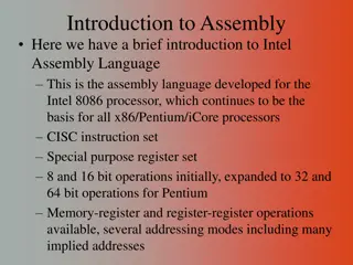
Assembly Language programming
DMA, or Direct Memory Access, is a method designed by Intel for fast data transfer between devices and memory. DMA controllers manage data transfer operations effectively, such as sending DMA requests, utilizing channels for I/O devices, and ensuring efficient communication between memory, CPU, and peripherals. The 8257 DMA controller features four channels, each with independent programming capabilities, high-speed data transfer, and specific pin descriptions for effective operation.

Download Presentation

Please find below an Image/Link to download the presentation.
The content on the website is provided AS IS for your information and personal use only. It may not be sold, licensed, or shared on other websites without obtaining consent from the author.If you encounter any issues during the download, it is possible that the publisher has removed the file from their server.
You are allowed to download the files provided on this website for personal or commercial use, subject to the condition that they are used lawfully. All files are the property of their respective owners.
The content on the website is provided AS IS for your information and personal use only. It may not be sold, licensed, or shared on other websites without obtaining consent from the author.
E N D
Presentation Transcript
Unit 2 Assembly Language programming By: Ms.ZEENATH Asst.Prof DEPT.OF ECE
DMA DMA stands for Direct Memory Access. It is designed by Intel to transfer data at the fastest rate. It allows the device to transfer the data directly to/from memory without any interference of the CPU. Using a DMA controller, the device requests the CPU to hold its data, address and control bus, so the device is free to transfer data directly to/from the memory. The DMA data transfer is initiated only after receiving HLDA signal from the CPU.
How DMA Operations are Performed? Following is the sequence of operations performed by a DMA Initially, when any device has to send data between the device and the memory, the device has to send DMA request (DRQ) to DMA controller. The DMA controller sends Hold request (HRQ) to the CPU and waits for the CPU to assert the HLDA. Then the microprocessor tri-states all the data bus, address bus, and control bus. The CPU leaves the control over bus and acknowledges the HOLD request through HLDA signal. Now the CPU is in HOLD state and the DMA controller has to manage the operations over buses between the CPU, memory, and I/O devices.
DMA CONTROLLER It is like a processor It has a capability of copying data from one location to another location at high speeds Transfer between memory & peripherals through s/w 3 states , modes i. Idle state not used by peripheral devices ii. Master mode: DMA ctrller is controlling the buses for data transfer b/w them iii. Slave mode or state mp read/write the DMA
Features of 8257 It has four channels which can be used over four I/O devices. Each channel has 16-bit address and 14-bit counter. Each channel can transfer data up to 64kb. Each channel can be programmed independently. Each channel can perform read transfer, write transfer and verify transfer operations. It generates MARK signal to the peripheral device that 128 bytes have been transferred. It requires a single phase clock. Its frequency ranges from 250Hz to 3MHz. It operates in 2 modes, i.e., Master mode and Slave mode.
DRQ0DRQ3 These are the four individual channel DMA request inputs, which are used by the peripheral devices for using DMA services. When the fixed priority mode is selected, then DRQ0has the highest priority and DRQ3has the lowest priority among them. DACKo DACK3 These are the active-low DMA acknowledge lines, which updates the requesting peripheral about the status of their request by the CPU. These lines can also act as strobe lines for the requesting devices.
Do D7:These are bidirectional, data lines which are used to interface the system bus with the internal data bus of DMA controller. In the Slave mode, it carries command words to 8257 and status word from 8257. In the master mode, these lines are used to send higher byte of the generated address to the latch. This address is further latched using ADSTB signal. IOR :It is an active-low bidirectional tri-state input line, which is used by the CPU to read internal registers of 8257 in the Slave mode. In the master mode, it is used to read data from the peripheral devices during a memory write cycle.
IOW : It is an active low bi-direction tri-state line CLK : It is a clock frequency signal which is required for the internal operation of 8257. RESET :This signal is used to RESET the DMA controller by disabling all the DMA channels.
Ao- A3:These are the four least significant address lines. In the slave mode, they act as an input, which selects one of the registers to be read or written. In the master mode, they are the four least significant memory address output lines generated by 8257. CS : It is an active-low chip select line. In the Slave mode, it enables the read/write operations to/from 8257. In the master mode, it disables the read/write operations to/from 8257.
A4- A7:These are the higher nibble of the lower byte address generated by DMA in the master mode. READY:It is an active-high asynchronous input signal, which makes DMA ready by inserting wait states. HRQ:This signal is used to receive the hold request signal from the output device. In the slave mode, it is connected with a DRQ input line 8257. In Master mode, it is connected with HOLD input of the CPU.
HLDA:It is the hold acknowledgement signal which indicates the DMA controller that the bus has been granted to the requesting peripheral by the CPU when it is set to 1. MEMR:It is the low memory read signal, which is used to read the data from the addressed memory locations during DMA read cycles. MEMW:It is the active-low three state signal which is used to write the data to the addressed memory location during DMA write operation.
ADST:This signal is used to convert the higher byte of the memory address generated by the DMA controller into the latches. AEN:This signal is used to disable the address bus/data bus. TC:It stands for Terminal Count , which indicates the present DMA cycle to the present peripheral devices.
MARK:The mark will be activated after each 128 cycles or integral multiples of it from the beginning. It indicates the current DMA cycle is the 128th cycle since the previous MARK output to the selected peripheral device. Vcc :is the power signal which is required for the operation of the circuit.