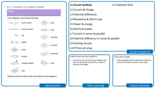
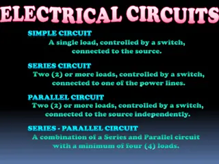
Basic Circuits and Circuit Symbols
A basic overview of circuits, symbols, and components like wires, cells, lamps, switches, and more. Learn about key figures like Benjamin Franklin and Thomas Edison who significantly contributed to understanding electricity. Explore the requirements of a circuit and understand the difference between complete and incomplete circuits.

Download Presentation

Please find below an Image/Link to download the presentation.
The content on the website is provided AS IS for your information and personal use only. It may not be sold, licensed, or shared on other websites without obtaining consent from the author.If you encounter any issues during the download, it is possible that the publisher has removed the file from their server.
You are allowed to download the files provided on this website for personal or commercial use, subject to the condition that they are used lawfully. All files are the property of their respective owners.
The content on the website is provided AS IS for your information and personal use only. It may not be sold, licensed, or shared on other websites without obtaining consent from the author.
E N D
Presentation Transcript
Basic Circuits I will be able to identify various circuit symbols I will be able to build a simple series circuit I will have a basic understanding of what happens in a cell
Starter Benjamin Franklin Thomas Edison This Photo by Unknown Author is licensed under CC BY This Photo by Unknown Author is licensed under CC BY-SA-NC Have you heard of these people? Why are they significant?
Benjamin Franklin Proved that lightning was electricity by flying a kite in a lightning storm Helped people understand the principles of electricity Thomas Edison Invented the electrical light bulb
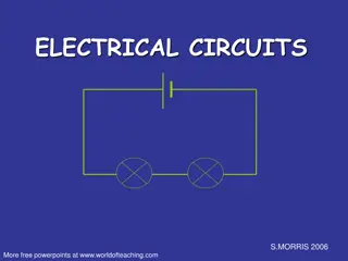
What is an Electrical Circuit? A circuit is an electrical device that provides a path for electricity to flow
Circuit diagrams A circuit is made up of two parts 1. Wires 2. Components
Wires are always draw as straight lines
What are the 3 requirements of a circuit? 1) a source of current 2) a set of conductors i.e. wires 3) a device that transforms electrical current into another form of energy i.e. a lightbulb
Complete or Incomplete? A complete circuit is where all the components of a circuit are joined up and there are no gaps The pathway for electricity is complete
Complete or Incomplete? An incomplete circuit is where the pathway for electricity is broken The electricity cannot flow
Complete these circuits, to see if the light comes on: a. Works: Does not work: Why? ___________________ ________________________ b. Works: Does not work: Why? ___________________ ________________________
c. Works: Does not work: Why? ___________________ ________________________
What are circuit diagrams? A circuit diagram is a graphical representation of an electrical circuit.
Why are circuit diagrams useful? Circuit diagrams show the connections as clearly as possible with all wires drawn neatly as straight lines.
The way in which components are arranged in a circuit can affect how they operate and how useful they are. Electric circuits can be series or parallel.
Circuit diagrams Battery or Cell Switch Bulb This is called a SERIES circuit
In a SERIES circuit, bulbs are added one after another in the same path. Battery or Cell Bulb Bulb
Series circuits In series circuits, electrical components are connected one after another in a single loop. Any break in the circuit will cause the whole circuit to stop working. Series circuits are found in torches and strings of Christmas lights.
Current in series The current is the same everywhere in a series circuit. It does not matter where you put the ammeter, it will give you the same reading.
All three ammeters read 0.5 A in this series circuit.
Voltage in a series circuit In a series circuit, the voltage supplied by the battery is shared by the components. So, the sum of the voltages across the components equals the battery voltage. As more bulbs are added in series, each bulb has less voltage and so the bulbs become dimmer.
In series circuits: current is the same through each component the total voltage of the power supply is shared between the components
Parallel circuits In a parallel circuit, different components are connected on different branches of the wire. If there is a break in the circuit in one loop, current can still flow through the other loop. Car headlights are wired in parallel.
Rules for voltage and current in parallel circuit The value of the supply current is the sum of the currents in the branches. The voltage across each branch is equal to the supply voltage.
State one advantage that a parallel circuit has over a series circuit. Kate is preparing to put the Christmas tree lights on the tree, and notices one is missing. The lamps will not work unless the missing one is replaced. Are the Christmas tree lights connected in series or parallel? Explain your answer.
Current A metal wire (conductor) contains electrons that move freely about inside the wire. When a wire is connected to a battery, the negatively charged electrons are pushed around the circuit in one direction.
An electric current is a movement of charge (electrons). The unit that is used to measure current is the ampere or Amps (A). A device called an ammeter is used to measure the current in a circuit.
Voltage in a circuit
Electrical circuits require an energy source. This can be provided by a cell, a battery or by mains electricity. The energy that can be provided by the energy source is the voltage. The voltage has two purposes: to push the charges around the circuit to supply the energy for the components to operate
Voltage is a measure of the energy given to electric charges in a circuit, and is given the symbol V. Voltage is measured in volts (V). Voltage is measured using a voltmeter.
A single battery is called a cell (1.5 V). A battery is a series of cells connected together. The value of the mains supply voltage is 230 V.
What have we learnt today? Have we met our learning objective today? What have I enjoyed today?