Basic Circuits and Slide Design: Today's Class and Tomorrow's Lab
Dive into the fundamentals of basic circuits and explore the principles of slide design. Prepare for Lab 2 in S365 by completing the prelab. Stay updated with the schedule for SE-28111. Engage with Dr. Mark L. Hornick's content across these topics.

Download Presentation

Please find below an Image/Link to download the presentation.
The content on the website is provided AS IS for your information and personal use only. It may not be sold, licensed, or shared on other websites without obtaining consent from the author.If you encounter any issues during the download, it is possible that the publisher has removed the file from their server.
You are allowed to download the files provided on this website for personal or commercial use, subject to the condition that they are used lawfully. All files are the property of their respective owners.
The content on the website is provided AS IS for your information and personal use only. It may not be sold, licensed, or shared on other websites without obtaining consent from the author.
E N D
Presentation Transcript
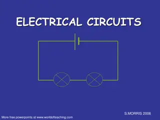
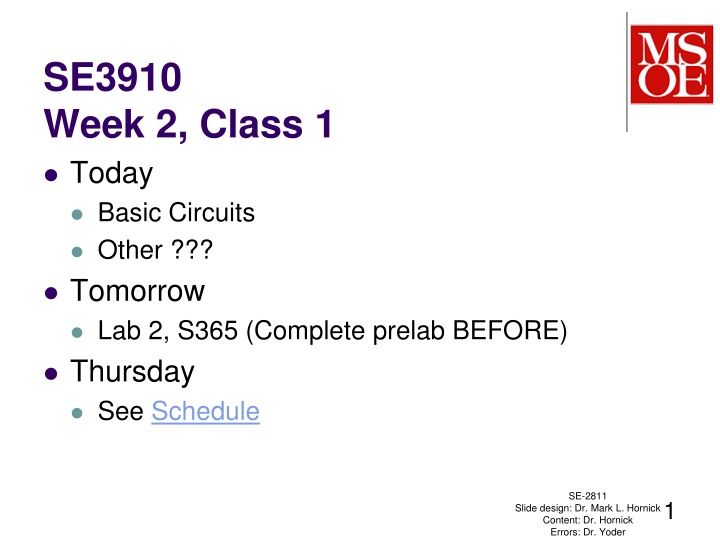
SE3910 Week 2, Class 1 Today Basic Circuits Other ??? Tomorrow Lab 2, S365 (Complete prelab BEFORE) Thursday See Schedule SE-2811 1 Slide design: Dr. Mark L. Hornick Content: Dr. Hornick Errors: Dr. Yoder
Warning Originally from: http://www.thegooglestory.com/glat.html http://xkcd.com/356/ SE-2811 Dr.Yoder 2
Cartoon One source: http://www.sengpielaudio.com/calculator ohmslaw.htm SE-2811 Dr.Yoder 3
Equipment (Reminder) This week: Purchase 4GB or greater micro SD card Used Lab 3 (Optional) Tools e.g. needle-noise pliers Check out short-term Kit (breakout board, breadboard cape, LCD cape, USB Oscilloscope) Small parts (also may desire to purchase) SE-2811 Dr.Yoder 4
Ex: Compute voltage across C1 If S1 is closed, and S2 is opened, what is the voltage across C1? If S2 is closed, and S1 is opened? If both are opened? If both are closed? SE-2811 Dr.Yoder 5
Ex: Compute voltage into GPIO If S1 is open and S2 is closed, compute the voltage from GPIO 12 to ground. (Assume GPIO 12 is not connected to anything) SE-2811 Dr. Yoder 6
A slightly better assumption if connected to a GPIO input SE-2811 Dr. Yoder 7
Warning 1: (Low risk) Input is like a (very small) capacitor Modern processors use CMOS technology These gates can look something like this on the inside: If left floating, can be any voltage If two switches use, can short source, so Dr. Yoder SE-2811 8
Solution 1: Use a pull-up or pull-down resistor (This is from Lab 2, you will analyze it there.) ( (See pp. 137-138 in E Exploring Beaglebone b by Derek Molloy, . 2015) SE-2811 Dr.Yoder 9
Warning 2: (Low risk) LEDs have constant voltage If you apply 3.3 V to a 2.10 V LED, it will be like applying 1.2 V directly to a short circuit Solution 2: Use limiting resistor Use a limiting resistor to fill up the rest of the voltage and set current. SE-2811 Dr. Yoder 10
Warning 3: (High risk) Do not short the GPIO pins to ground or 3.3V when they are in output mode. SE-2811 11 Slide design: Dr. Mark L. Hornick Content: Dr. Hornick Errors: Dr. Yoder
Solution 3: Do not place beaglebone on metal surface (e.g. aluminum-finish laptop) [EB, p. 21] Ensure beaglebone is correctly configured before powering If circuit provides input, beaglebone MUST NOT provide output When using output, your circuit should not Source more than 4mA (current out of bone) Sink more than 8mA (current into bone) for any given GPIO pin. Dr.Yoder SE-2811 12
Warning 4: (High risk) Beaglebone is 3.3 V Supplying 5 V to any GPIO pin could damage it. Furthermore, supplying even 3.3 V to a pin without powering the board could damage it. SE-2811 Dr.Yoder 13
Solution 4: Always use the 3.3 V supply Never use external power use the 3.3 V supplied Unless you know what you are doing! May need to use voltage converters from external signals. Or at least external logic enabled by the 3.3V supply SE-2811 Dr.Yoder 14
Warning 5: (Medium risk) Do not unplug beaglebone while running Residual currents can result in higher residual voltages Memory might be saved in inconsistent state Solution 5: Hold down power button until all lights turn off If you must, hold down reset button (which forces the bone off) while unplugging. SE-2811 Dr.Yoder 15
Warning 6: Hard to pick the right pin You can, e.g. easily plug into 5V when you mean to plug in to 3.3V. Solution 6: Print labels for your pins tiny.cc/ebb105 [EB, p. 21] Use the breakout cape It has labels already printed Google beaglebone black pinout SE-2811 16 Slide design: Dr. Mark L. Hornick Content: Dr. Hornick Errors: Dr. Yoder
Warning 7: Analog limit No more than 1.8 V into analog pin Solution 7: Use the supplied 1.8 V supply as power for analog devices Ensure devices are not configured in analog before plugging into POTENTIALLY analog pins Content: Dr. Hornick Errors: Dr. Yoder SE-2811 17 Slide design: Dr. Mark L. Hornick
Warning 8: Dont pull SD card If you pull out the card, it could cause damage Solution 8: Push in the card, and it will push itself out (never fails ) SE-2811 18 Slide design: Dr. Mark L. Hornick Content: Dr. Hornick Errors: Dr. Yoder
Warning 9: Other things If you are working on a very complicated circuit, please see the (un)official System Reference Manual Solution And read all the red text (I have a summary file, if you want ) SE-2811 19 Slide design: Dr. Mark L. Hornick Content: Dr. Hornick Errors: Dr. Yoder
GPIO safety (summary of a few key points) Sourcing limit: 4mA Limit if current is coming OUT OF Beaglebone Sinking limit: 8mA Limit if current is flowing INTO Beaglebone Digital Voltage: 3.3 V Analog input max voltage: 1.8 V SE-2811 Dr.Yoder 20
Ex: What is the resistance of this resistor? SE-3910 - Dr. Josiah Yoder Slide style: Dr. Hornick Much Material: Dr. Schilling 21
References EB: Derek Malloy, Exploring Beaglebone, Wiley, 2015 SE-2811 22 Slide design: Dr. Mark L. Hornick Content: Dr. Hornick Errors: Dr. Yoder


")


")

")
")

")

")