Basic Circuits Lab Overview and Components

This guide provides a comprehensive overview of basic circuit components and their functions. It covers essential elements such as batteries, resistors, LEDs, and potentiometers, explaining their roles in electrical circuits. Understanding voltage, current, and resistance is crucial for prototyping designs on solderless breadboards. Explore LED lighting circuits, variable resistors, and the principles of Ohm's Law to grasp foundational concepts essential for circuit design and experimentation.

Download Presentation

Please find below an Image/Link to download the presentation.
The content on the website is provided AS IS for your information and personal use only. It may not be sold, licensed, or shared on other websites without obtaining consent from the author.If you encounter any issues during the download, it is possible that the publisher has removed the file from their server.
You are allowed to download the files provided on this website for personal or commercial use, subject to the condition that they are used lawfully. All files are the property of their respective owners.
The content on the website is provided AS IS for your information and personal use only. It may not be sold, licensed, or shared on other websites without obtaining consent from the author.
E N D
Presentation Transcript
Basic Circuits Lab 1 Xmedia Spring 2012
Basically Power Provides energy for the sensor and the output Sensor Changes aspects of the circuit based on input Output Changes based on the sensor
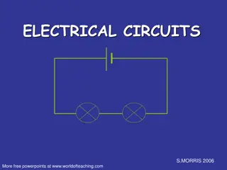
Lighting an LED Battery Resistor LED
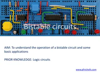
Solderless Breadboards Used to prototype circuit designs
Battery Potential Difference - Voltage Like potential energy Positive (VCC, +) and negative (Ground, ) Note about complete circuits 9 Volts 1.5 Volts
Resistor Resistance Ohms Limits the current
LED Light Emitting Diode Directional Brightness based on current
Lighting an LED Build this circuit Observe the light turn on when you complete the circuit
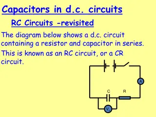
Fading and LED Battery Resistor Potentiometer LED
Potentiometer Variable resistor Changes the resistance in the circuit Positive, negative, and variable legs
Some Theory Voltage Resistance Current Ohm s Law Calculating LED Resistor Values
Voltage V Potential difference Energy per unit charge Drives the current between two points in a circuit V DC V~ AC
Current A~ AC A DC I Flow of unit charge per unit time Ampere Coulombs/second
Resistance R, Opposition to the flow of current Based on properties of the material Conductor vs. Insulator
Ohms Law Relates voltage, current and resistance I = V / R V = I * R Units are important amperes, ohms, volts Not milliamps, and millivolts
Calculating LED Resistor Values LED Voltage and Current from data sheet Typically ~ 1.7V Typically ~ 20mA Know supply voltage for example 5V Resistor needs to take the extra voltage 5 1.7 = 3.3 V Ohm s Law R = V/I = 3.3V/0.02A = 165
Multimeter Usage Connections: Black - COM / Ground Red - 10A, 300mA, V/Ohms Continuity Test, Diode Test, Resistance, Voltage, Current Specs: DC voltage range: 326mV - 1000V AC voltage range: 3.26V - 750V DC/AC current range: 326 A -10A Resistance range: 326ohm - 32.6Mohm Mastech MY68 Autoranging
Multimeter Usage Continuity Test To check if two points are electrically connected, audible beep sounds if they are Diode Test Diodes only allow current to flow in one direction only, they have a positive (+) lead (i.e. anode) and a negative (-) lead (i.e. cathode) LEDs are diodes that emit light You can test the polarity of a diode using a multimeter set to "diode test" mode Connect the black lead to (-) and the red lead to (+) and the diode will conduct. Connected backwards it will not.
Multimeter Usage Note: in manual range mode, always make sure to select the correct range before connecting the multimeter leads!! Resistance - Remove component from the circuit Voltage - V At a point in a complete circuit Connect black lead to ground, red lead to the point in the circuit V DC V~ AC
Multimeter Usage Current - A Use the 10A jack until you're sure that the current is less than 300mA, and set the range before connecting the leads! Current is measured in series with the circuit: Turn off the power Break the circuit Put the meter in series Turn the power on A DC A~ AC
Fading an LED Build this circuit Turn the knob Observe the LED changing brightness
Lighting 3 LEDs in Parallel Do this on your own. Build this circuit. Measure the voltage across each branch. Measure the current out of the battery and before each LED.
Current Split - Parallel Sum of the current through each branch equals the current from the power source Voltages are the same in each branch 1/Rtotal = 1/R1 + 1/R2+ + 1/Rn
Lighting 3 LEDs in Series Do this on your own. Build this circuit. Measure the voltage across each LED. Measure the current out of the battery and before each LED.
Voltage Split - Series Voltage across each component is different Current through each component is the same Rtotal = R1 + R2 + . . . + Rn
Voltage Divider Vout = Vin * R3 / (R1 + R3) If R1 is variable, as R1 increases Vout decreases
Calculating Resistance Series Rtotal = R1 + R2 + . . . + Rn Paralell 1/Rtotal = 1/R1 + 1/R2+ + 1/Rn
Variable Power Supply Output connections in Volts DC (direct current) Red: power Black: ground Specifications: 1.5 to 30V DC output 0 to 1A output current 100 to 240V AC input Over-voltage/current protection Short circuit protection