Basic Electronic Operational Amplifiers and Their Characteristics
Learn about operational amplifiers (Op-Amps), their functions in electronic circuits, characteristics, ideal behavior, saturation points, and analysis. Discover the concept of voltage gain and how to implement inverting amplifiers with practical examples.

Download Presentation

Please find below an Image/Link to download the presentation.
The content on the website is provided AS IS for your information and personal use only. It may not be sold, licensed, or shared on other websites without obtaining consent from the author. If you encounter any issues during the download, it is possible that the publisher has removed the file from their server.
You are allowed to download the files provided on this website for personal or commercial use, subject to the condition that they are used lawfully. All files are the property of their respective owners.
The content on the website is provided AS IS for your information and personal use only. It may not be sold, licensed, or shared on other websites without obtaining consent from the author.
E N D
Presentation Transcript
Basic Electronic Operational Amplifier
Operational Amplifier Operational Amplifier An Operational Amplifier (Op-Amp) is an integrated circuit that uses external voltage to amplify the input through a very high gain.
Operational Amplifier Operational Amplifier The actual count varies, but an Op-Amp contains several Transistors, Resistors, and a few Capacitors and Diodes. For simplicity, an Op-Amp is often depicted as this: Positive Power Supply Inverting Input - Output + Non- Inverting Input Negative Power Supply
741 Op 741 Op- -Amp Schematic Amp Schematic
Voltage Gain Voltage Gain The gain of the Op-Amp itself is calculated as: G = Vout/(V+ V-) The maximum output is the power supply voltage When used in a circuit, the gain of the circuit (as opposed to the op-amp component) is: Av = Vout/Vin
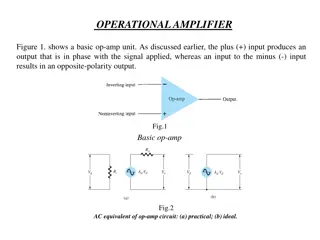
Op Op- -Amp Saturation Amp Saturation The maximum output value is the supply voltage, positive and negative. The gain (G) is the slope between saturation points. Vout Vs+ Ideal op-amp + AVin ~ Vin Vout Vin Zout=0 Vs-
Ideal Op Ideal Op- -Amp Characteristics Amp Characteristics Open-loop gain G is infinite Rin is infinite Zero input current Rout is zero
Ideal Op Ideal Op- -Amp Analysis Amp Analysis To analyze an op-amp feedback circuit: Assume no current flows into either input terminal Assume no current flows out of the output terminal Constrain: V+ = V-
Inverting Amplifier Inverting Amplifier Rf (1) Kirchhoff node equation at V+ yields, 0 = + V Ra Vo ~ Vin Kirchhoff node equation at V yields, _ in R (2) + V V R V V + = 0 o a f (3) Setting V+ = V yields V = R f o Notice: The closed-loop gain Vo/Vin is dependent upon the ratio of two resistors, and is independent of the open-loop gain. This is caused by the use of feedback output voltage to subtract from the input voltage. V R in a 9
Noninverting Amplifier Noninverting Amplifier (1) Kirchhoff node equation at V+ yields, V = + Vin + Vo iV Kirchhoff node equation at V yields, 0 + a R (2) Rf Ra R V V V = 0 o f (3) Setting V+ = V yields R R V V V V f =1 + + or 0 = o i i o R V R a f i a
Summing Amplifier Summing Amplifier (1) Kirchhoff node equation at V+ yields, 0 = + V Rf Ra Va Vb Vc Rb Rc Vo Kirchhoff node equation at V yields, (2) + V V R R R V V V V V V _ o + + + = 0 a b c R f a b c (3) Setting V+ = V yields = f o R V V c V V V = j j + + = a b c R f R R R R a a b c j 11
Op Op- -Amp Buffer Amp Buffer Vout = Vin Isolates loading effects B A Low input impedance High output impedance
Op Op- -Amp Differentiator Amp Differentiator R C 0to Vi t1 t2 Vo 0 + t2 t1 to 13
Op Amp Integrator Op Amp Integrator
Op Op- -Amp Differential Amplifier Amp Differential Amplifier If R1 = R2 and Rf = Rg:
Common Common- -Mode Rejection Ratio Mode Rejection Ratio (CMRR) (CMRR) Differential voltage input : + = V V Vd Noninverting Input + Output Inverting Input Common voltage input : 1 = V Vc ++ ( ) V 2 Common-mode rejection ratio: G G = = d d CMRR 20 log ( dB ) Output voltage : = 10 G G c c + V G V G V o d d c c Note: When Gd >> Gc or CMRR Vo = GdVd Gd : Differential gain Gc : Common mode gain 16
Ideal and Practical Op Ideal and Practical Op- -Amp Amp Ideal op-amp + AVin ~ Vin Vout Zout=0 Practical op-amp + Zout Zin Vout Vin ~ AVin