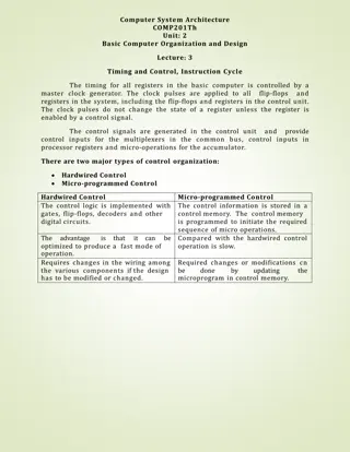
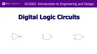
Basic Logic Gates in Computer Science
The foundational blocks of digital logic, including AND, OR, NOT, NAND, NOR, EX-OR gates, and Half Adder operation. Dive into truth tables and circuit realizations.

Uploaded on Mar 08, 2025 | 0 Views
Download Presentation

Please find below an Image/Link to download the presentation.
The content on the website is provided AS IS for your information and personal use only. It may not be sold, licensed, or shared on other websites without obtaining consent from the author.If you encounter any issues during the download, it is possible that the publisher has removed the file from their server.
You are allowed to download the files provided on this website for personal or commercial use, subject to the condition that they are used lawfully. All files are the property of their respective owners.
The content on the website is provided AS IS for your information and personal use only. It may not be sold, licensed, or shared on other websites without obtaining consent from the author.
E N D
Presentation Transcript
BY GAWARE S.R. COMPUTER SCIENCE DEPARTMENT
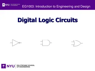
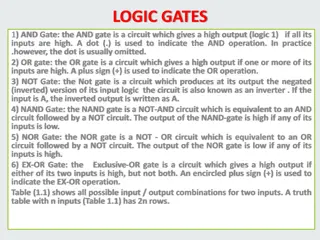
Basic Logic Gates Logic gates constitute the foundation blocks for digital logic. Let us start by reviewing these gates and their truth tables: 1. AND Gate An AND Gate has two or more inputs and produces one output as follows: output = 1 if all of the inputs are high, output = 0 if one or more of the inputs are low [1]. An OR gate also has two or more inputs and produces one output as follows: output = 1 if one or more inputs are high, output = 0 if all inputs are low [1]:
2. OR Gate: An OR gate also has two or more inputs and produces one output as follows: output = 1 if one or more inputs are high, output = 0 if all inputs are low [1]:
3.NOT Gate: The inverter gate has one input and produces one output as follows: output =1 if input is low, output = 0 if input is high [1]. 4. The NAND gate has two or more inputs and produces one output as follows: output = 0 if all the inputs are high, output = 1 if any of the inputs are low [1]
5. NOR Gate: The NOR gate has two or more inputs and produces one output as follows: output = 1 if all inputs are low, output = 0 if any of the inputs is high [1]. 6. EX-OR Gate: The Exclusive-OR gate always has two inputs only and produces one output as follows: output = 1 when inputs are not similar, output = 0 when inputs are the same [1].
7. EX-NOR Gate: The Exclusive-NOR gate always has two inputs only and produces one output as follows: output = 1 when inputs are both high or are both low, output = 0 when inputs are not similar [1].
Half Adder: Adding two single-bit binary values X, Y produces a sum S bit and a carry out C-out bit. This operation is called half addition and the circuit to realize it is called a half adder. TRUTH TABLE X X 0 0 1 1 Y Y 0 1 0 1 SUM 0 1 1 0 SUM CARRY 0 0 0 1 CARRY SYMBOL
S (X,Y) = (1,2) S = X'Y + XY' S = XY CARRY(X,Y) = (3) CARRY = XY CIRCUIT
Full Adder Full adder takes a three-bits input. Adding two single-bit binary values X, Y with a carry input bit C-in produces a sum bit S and a carry out C-out bit. Truth Table X 0 0 0 0 1 1 1 1 Y 0 0 1 1 0 0 1 1 Z 0 1 0 1 0 1 0 1 SUM 0 1 1 0 1 0 0 1 CARRY 0 0 0 1 0 1 1 1


 = (1,2)")