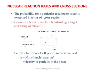
Beam Attenuation Measurement Reality
Explore uncertainties in scattering, attenuation, and tracking for calibration and validation of beam attenuation measurements. Learn about the impact of detector acceptance angles on accuracy and consider instrumental and sample factors affecting measurements. Delve into issues with attenuation and scattering measurement theory. Examine the volume scattering function and challenges related to in-situ IOP measurements.

Download Presentation

Please find below an Image/Link to download the presentation.
The content on the website is provided AS IS for your information and personal use only. It may not be sold, licensed, or shared on other websites without obtaining consent from the author.If you encounter any issues during the download, it is possible that the publisher has removed the file from their server.
You are allowed to download the files provided on this website for personal or commercial use, subject to the condition that they are used lawfully. All files are the property of their respective owners.
The content on the website is provided AS IS for your information and personal use only. It may not be sold, licensed, or shared on other websites without obtaining consent from the author.
E N D
Presentation Transcript
Scattering and attenuation and tracking uncertainties for cal/val
Beam Attenuation Measurement Reality c = (-1/x)ln( t/ o) source detector a b t o x Detected flux ( t) measurement must exclude scattered flux
Beam Attenuation Measurement Reality c = (-1/x)ln( t/ o) The size of the detector acceptance angle (FOV) determines the retrieved value of c source a b t o x The larger the detector acceptance angle, the more scattered flux detected as t, the smaller the estimated value of c
Ex. transmissometer/c-meter FOV 0.018o 0.7o 0.86o 1.5o Direct impact on accuracy of measured beam c % b detected <1 ~ 5 ~ 7 ~14 Large d /d in near forward angles
VSF measurements with LISST-Floc: Boss et al., 2009a
Instrumental and sample considerations affecting our measurements, beam-attenuation acceptance-angle example: Acceptance Angles 0.93 0.0269 0.0045 Boss et al., 2009a
Issues with attenuation: 1. Magnitude depends on the acceptance angle. 2. Because of that -> size filter. 3. Does not need other corrections (+++). 4. Path-length need to be adjusted to environment. Recent analysis: Leymarie et al., 2010 (AO)
Scattering Measurement Theory b = fractional scatterance per unit distance b Scattered Radiant Flux a o t b = (-1/x)ln [ t / o] (-1/x)ln [ a / o] = c - a
Volume Scattering Function () ( ) = (-1/x d )ln[ b( )/ o] b= d detector b/ source a o
Issues with the VSF: Fundamental in-situ IOP (as important as absorption!). No commercial sensor for full (bench-top exist). Issues of packaging (in-situ undistrubed vs. handled samples)
Volume Scattering Measurements ( ) = (-1/x d )ln[ b( )/ o] Detected flux measurement must correct for attenuated flux along pathlength inner-filter effect x Define shape of detection area Calibration with known substance mathematically b ( ) o source detector
Most often backscattering in inferred from one angle in the back direction. Why: Boss and Pegau, 2001
Bottom line: But (2005):
Sullivan and Twardowski (2009): Consistency from 90->150degrees (except for one study ).
Whitmire et al. (2010): Phytoplankton cultures (6 ):
How should we go ahead and characterize the uncertainty in a backscattering sensor? ( ) ( ) 0, = Slope Signal Dark 0 Signal and Dark values are measured in counts. The Dark value is system dependent (due to impedance of circuit) . Current reported uncertainty: slope 1 count. ( ) b = 2 0, 0 bp p p Uncertainty in p ~10%. Uncertainty in
Calibration is done with 2m NIST traceable polystyrene beads, whose phase function is:
How is the wavelength distribution for the bb sensors? 1 0.9 0.8 0.7 LED Relative Response 0.6 0.5 0.4 0.3 0.2 0.1 0 350 400 450 500 550 600 650 700 750 800 Wavelength [nm] Normalized source output for MISC s bb9 (solid line) vs. that provided by WETLabs (dashed line). Currently, slope calculations assume wavelength is constant
How about the angle distribution? 1 0.9 0.8 Nomalized angular response 0.7 0.6 0.5 0.4 0.3 0.2 0.1 0 60 80 100 Scattering angle [degree] 120 140 160 180 Currently, slope calculations assume angle is constant
Issues with scattering: 1. Attenuation along the path (---). 2.Knowledge of geometry and wavelength. 3.calibration. 4.Conversion from angle(s) to backscattering involve significant uncertainties.


")


:")
:")