Learn about the major applications of Bipolar Junction Transistors (BJTs) as switches and amplifiers. Explore how a BJT functions as a switch, alternating between cutoff and saturation for digital circuits, and discover the amplification process of linearly increasing electrical signals using a BJT. Understand the distinction between DC and AC quantities in transistor circuits and the voltage amplification mechanism in BJT amplifier circuits.
Please find below an Image/Link to download the presentation.
The content on the website is provided AS IS for your information and personal use only. It may not be sold, licensed, or shared on other websites without obtaining consent from the author. If you encounter any issues during the download, it is possible that the publisher has removed the file from their server.
You are allowed to download the files provided on this website for personal or commercial use, subject to the condition that they are used lawfully. All files are the property of their respective owners.
The content on the website is provided AS IS for your information and personal use only. It may not be sold, licensed, or shared on other websites without obtaining consent from the author.
E N D
Presentation Transcript
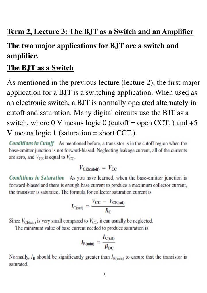
Term 2, Lecture 3: The BJT as a Switch and an Amplifier The two major applications for BJT are a switch and amplifier. The BJT as a Switch As mentioned in the previous lecture (lecture 2), the first major application for a BJT is a switching application. When used as an electronic switch, a BJT is normally operated alternately in cutoff and saturation. Many digital circuits use the BJT as a switch, where 0 V means logic 0 (cutoff = open CCT. ) and +5 V means logic 1 (saturation = short CCT.). 1
Cfsat) Cfsat) o vo VA (a) Cutoff open switch (b) Saturation dosed switch 2
The BJT as an Amplifier: Amplification is the process of linearly increasing the amplitude of an electrical signal and is one of the major properties of a transistor. As you learned, a BJT exhibits current gain (called beta). When a BJT is biased in the active (or linear) region, as previously described, the BE junction has a low resistance due to forward bias and the BC junction has a high resistance due to reverse bias. DC and AC Quantities: Before discussing the concept of transistor amplification, the designations that we will use for the circuit quantities of current, voltage, and resistance must be explained because amplifier circuits have both dc and ac quantities. DC quantities always carry an uppercase (large letter) subscript. For example, IB, IC, and IEare the dc transistor currents. VBE, VCB, and VCEare the dc voltages from one transistor terminal to another. Single subscripted voltages such as VB, VC, and VEare dc voltages from the transistor terminals to ground. Ac quantities always carry a lowercase (small letter) subscript. For example, Ib, Ic, and Ie are the ac transistor currents. Vbe, Vcb, and Vce are the ac voltages from one transistor terminal to 3
another. Single subscripted voltages such as Vb, Vc, and Ve are ac voltages from the transistor terminals to ground. Circuit resistances external to the transistor itself use the standard capital R with a subscript that identifies the resistance as dc or ac, for example RE is an external dc emitter resistance and Re is an external ac emitter resistance. Also we shall use the internal ac emitter resistance is designated as . Voltage Amplification As you have learned, a transistor amplifies current because the collector current is equal to the base current multiplied by the current gain, beta. The base current in a transistor is very small compared to the collector and emitter currents. Because of this, the collector current is approximately equal to the emitter current. Figure below shows basic transistor amplified circuit, where an ac voltage, Vin, is superimposed on the dc bias voltage VBB and the dc bias voltage VCC is connected to the collector through the collector resistor, RC. 4
The ac input voltage produces an ac base current, which results in a much larger ac collector current. The ac collector current produces an ac voltage across Rc, thus producing an amplified, but inverted, as illustrated in Figure above. In this amplifier, when base voltage increase, base current increases. It also causes an increase in the collector current which in turn causes a voltage drop in the collector resistor RC. Because the output is situated below the collector resistance RC, the output voltage will decrease as voltage drop across collector resistor increase. Thus it produces a 180 phase shift. (input positive, output negative and vice versa). 5
Review Questions : 1. When a transistor is used as a switch, in what two states is it operated? 2. When is the collector current maximum? 3. When is the collector current approximately zero? 6
4. Under what condition is VCE =VCC? 5. When is VCE minimum? 6. What is amplification? 7. How is voltage gain defined? 8. Name two factors that determine the voltage gain of an amplifier. 7


")