BOBCAT 335 COMPACT EXCAVATOR Service Repair Manual Instant Download (SN A16U11001 & Above)
BOBCAT 335 COMPACT EXCAVATOR Service Repair Manual Instant Download (SN A16U11001 & Above)

Download Presentation

Please find below an Image/Link to download the presentation.
The content on the website is provided AS IS for your information and personal use only. It may not be sold, licensed, or shared on other websites without obtaining consent from the author. If you encounter any issues during the download, it is possible that the publisher has removed the file from their server.
You are allowed to download the files provided on this website for personal or commercial use, subject to the condition that they are used lawfully. All files are the property of their respective owners.
The content on the website is provided AS IS for your information and personal use only. It may not be sold, licensed, or shared on other websites without obtaining consent from the author.
E N D
Presentation Transcript
Service Manual 335 Compact Excavator S/N A16U11001 & Above Printed in U.S.A. Bobcat Company 2007 6904775 (12-07)
MAINTENANCE SAFETY Instructions are necessary before operating or servicing machine. Read and understand the Operation & Maintenance Manual, Operator s Handbook and signs (decals) on machine. Follow warnings and instructions in the manuals when making repairs, adjustments or servicing. Check for correct function after adjustments, repairs or service. Untrained operators and failure to follow instructions can cause injury or death. WARNING W-2003-0903 Safety Alert Symbol: This symbol with a warning statement, means: Warning, be alert! Your safety is involved! Carefully read the message that follows. CORRECT CORRECT CORRECT B-10731A B-19964 B-19959 Never service the Bobcat Compact Excavator without instructions. Cleaning and maintenance are required daily. Use the correct procedure to lift and support the excavator. WRONG WRONG WRONG B-19965 B-19966 B-19960 Always lower the bucket and blade to the ground before doing any maintenance. Never modify equipment or add attachments not approved by Bobcat Company. Have welding or grinding painted parts. Wear dust mask when grinding painted parts. Toxic dust and gas can be produced. good ventilation when Vent exhaust to outside when engine must be run for service. Exhaust system must be tightly sealed. Exhaust fumes can kill without warning. WRONG WRONG WRONG B-19958 B-19798 B-19962 Lead-acid flammable and explosive gases. Keep arcs, sparks, flames and lighted tobacco batteries. Batteries contain acid which burns eyes or skin on contact. Wear protective clothing. If acid contacts body, flush well with water. For eye contact flush well and get immediate attention. batteries produce Stop, cool and clean engine of flammable materials checking fluids. Never service or adjust machine with the engine running unless instructed to do so in the manual. Avoid contact hydraulic fluid or diesel fuel under pressure. It can penetrate the skin or eyes. Never fill fuel tank with engine running, while smoking, or when near open flame. Maintenance procedures which are given in the Operation & Maintenance Manual can be performed by the owner/ operator without any specific technical training. Maintenance procedures which are not in the Operation & Maintenance Manual must be performed ONLY BY QUALIFIED BOBCAT SERVICE PERSONNEL. Always use genuine Bobcat replacement parts. The Service Safety Training Course is available from your Bobcat dealer. Keep body, jewelry and clothing away from moving parts, electrical contact, hot parts and exhaust. Wear eye protection to guard from battery acid, compressed springs, fluids under pressure and flying debris when engines are running or tools are used. Use eye protections approved for type of welding. Keep tailgate closed except for service. Close and latch tailgate before operating the excavator. before away from with leaking medical MSW28-0805
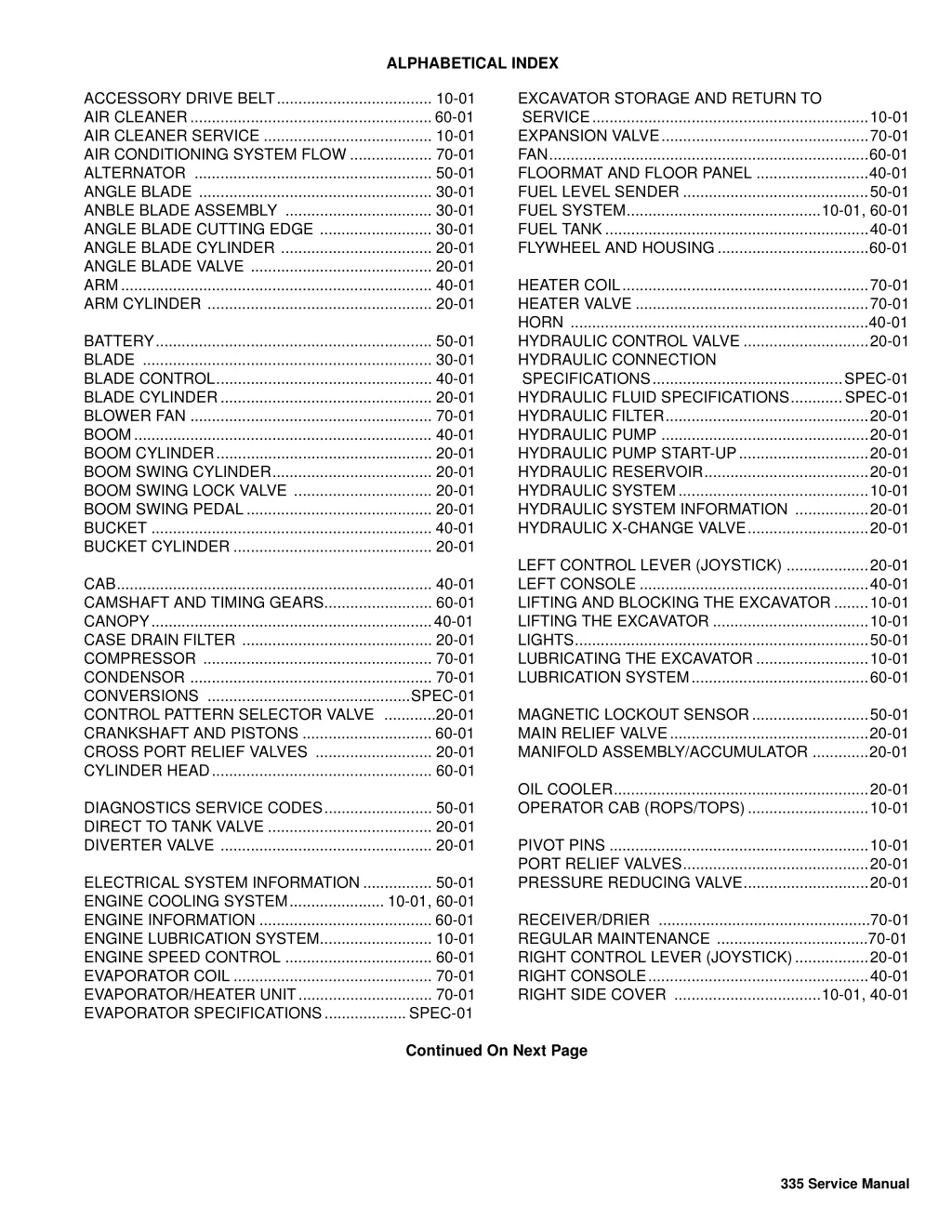
ALPHABETICAL INDEX EXCAVATOR STORAGE AND RETURN TO SERVICE................................................................10-01 EXPANSION VALVE................................................70-01 FAN..........................................................................60-01 FLOORMAT AND FLOOR PANEL ..........................40-01 FUEL LEVEL SENDER ...........................................50-01 FUEL SYSTEM.............................................10-01, 60-01 FUEL TANK.............................................................40-01 FLYWHEEL AND HOUSING...................................60-01 ACCESSORY DRIVE BELT.................................... 10-01 AIR CLEANER........................................................60-01 AIR CLEANER SERVICE ....................................... 10-01 AIR CONDITIONING SYSTEM FLOW ................... 70-01 ALTERNATOR ....................................................... 50-01 ANGLE BLADE ...................................................... 30-01 ANBLE BLADE ASSEMBLY .................................. 30-01 ANGLE BLADE CUTTING EDGE .......................... 30-01 ANGLE BLADE CYLINDER ................................... 20-01 ANGLE BLADE VALVE .......................................... 20-01 ARM........................................................................ 40-01 ARM CYLINDER .................................................... 20-01 HEATER COIL.........................................................70-01 HEATER VALVE ......................................................70-01 HORN .....................................................................40-01 HYDRAULIC CONTROL VALVE .............................20-01 HYDRAULIC CONNECTION SPECIFICATIONS............................................SPEC-01 HYDRAULIC FLUID SPECIFICATIONS............SPEC-01 HYDRAULIC FILTER...............................................20-01 HYDRAULIC PUMP ................................................20-01 HYDRAULIC PUMP START-UP..............................20-01 HYDRAULIC RESERVOIR......................................20-01 HYDRAULIC SYSTEM............................................10-01 HYDRAULIC SYSTEM INFORMATION .................20-01 HYDRAULIC X-CHANGE VALVE............................20-01 BATTERY................................................................ 50-01 BLADE ................................................................... 30-01 BLADE CONTROL.................................................. 40-01 BLADE CYLINDER................................................. 20-01 BLOWER FAN ........................................................ 70-01 BOOM..................................................................... 40-01 BOOM CYLINDER.................................................. 20-01 BOOM SWING CYLINDER..................................... 20-01 BOOM SWING LOCK VALVE ................................ 20-01 BOOM SWING PEDAL........................................... 20-01 BUCKET ................................................................. 40-01 BUCKET CYLINDER .............................................. 20-01 LEFT CONTROL LEVER (JOYSTICK) ...................20-01 LEFT CONSOLE .....................................................40-01 LIFTING AND BLOCKING THE EXCAVATOR........10-01 LIFTING THE EXCAVATOR ....................................10-01 LIGHTS....................................................................50-01 LUBRICATING THE EXCAVATOR ..........................10-01 LUBRICATION SYSTEM.........................................60-01 CAB......................................................................... 40-01 CAMSHAFT AND TIMING GEARS......................... 60-01 CANOPY.................................................................40-01 CASE DRAIN FILTER ............................................ 20-01 COMPRESSOR ..................................................... 70-01 CONDENSOR ........................................................ 70-01 CONVERSIONS ...............................................SPEC-01 CONTROL PATTERN SELECTOR VALVE ............20-01 CRANKSHAFT AND PISTONS .............................. 60-01 CROSS PORT RELIEF VALVES ........................... 20-01 CYLINDER HEAD................................................... 60-01 MAGNETIC LOCKOUT SENSOR...........................50-01 MAIN RELIEF VALVE..............................................20-01 MANIFOLD ASSEMBLY/ACCUMULATOR .............20-01 OIL COOLER...........................................................20-01 OPERATOR CAB (ROPS/TOPS)............................10-01 DIAGNOSTICS SERVICE CODES......................... 50-01 DIRECT TO TANK VALVE ...................................... 20-01 DIVERTER VALVE ................................................. 20-01 PIVOT PINS ............................................................10-01 PORT RELIEF VALVES...........................................20-01 PRESSURE REDUCING VALVE.............................20-01 ELECTRICAL SYSTEM INFORMATION................ 50-01 ENGINE COOLING SYSTEM...................... 10-01, 60-01 ENGINE INFORMATION ........................................ 60-01 ENGINE LUBRICATION SYSTEM.......................... 10-01 ENGINE SPEED CONTROL .................................. 60-01 EVAPORATOR COIL .............................................. 70-01 EVAPORATOR/HEATER UNIT............................... 70-01 EVAPORATOR SPECIFICATIONS...................SPEC-01 RECEIVER/DRIER .................................................70-01 REGULAR MAINTENANCE ...................................70-01 RIGHT CONTROL LEVER (JOYSTICK).................20-01 RIGHT CONSOLE...................................................40-01 RIGHT SIDE COVER ..................................10-01, 40-01 Continued On Next Page 335 Service Manual
https://www.ebooklibonline.com Hello dear friend! Thank you very much for reading. Enter the link into your browser. The full manual is available for immediate download. https://www.ebooklibonline.com
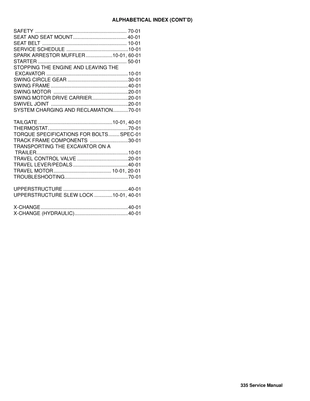
ALPHABETICAL INDEX (CONTD) SAFETY ................................................................. 70-01 SEAT AND SEAT MOUNT...................................... 40-01 SEAT BELT ............................................................ 10-01 SERVICE SCHEDULE ............................................10-01 SPARK ARRESTOR MUFFLER...................10-01, 60-01 STARTER ............................................................... 50-01 STOPPING THE ENGINE AND LEAVING THE EXCAVATOR ..........................................................10-01 SWING CIRCLE GEAR...........................................30-01 SWING FRAME.......................................................40-01 SWING MOTOR .....................................................20-01 SWING MOTOR DRIVE CARRIER..........................20-01 SWIVEL JOINT .......................................................20-01 SYSTEM CHARGING AND RECLAMATION...........70-01 TAILGATE.....................................................10-01, 40-01 THERMOSTAT.........................................................70-01 TORQUE SPECIFICATIONS FOR BOLTS........SPEC-01 TRACK FRAME COMPONENTS ...........................30-01 TRANSPORTING THE EXCAVATOR ON A TRAILER.................................................................10-01 TRAVEL CONTROL VALVE ....................................20-01 TRAVEL LEVER/PEDALS.......................................40-01 TRAVEL MOTOR......................................... 10-01, 20-01 TROUBLESHOOTING.............................................70-01 UPPERSTRUCTURE ..............................................40-01 UPPERSTRUCTURE SLEW LOCK .............10-01, 40-01 X-CHANGE..............................................................40-01 X-CHANGE (HYDRAULIC)......................................40-01 335 Service Manual
SAFETY AND MAINTENANCE CONTENTS FOREWORD. . . . . . . . . . . . . . . . . . . . . . . . . . . . . . . . . . . . . . . . . . . III SAFETY INSTRUCTIONS . . . . . . . . . . . . . . . . . . . . . . . . . . . . . . . . V HYDRAULIC SYSTEM SERIAL NUMBER LOCATIONS . . . . . . . . . . . . . . . . . . . . . . . . . . . .IX DELIVERY REPORT. . . . . . . . . . . . . . . . . . . . . . . . . . . . . . . . . . . . . X UNDERCARRIAGE EXCAVATOR IDENTIFICATION . . . . . . . . . . . . . . . . . . . . . . . . . . . .XI SAFETY AND MAINTENANCE. . . . . . . . . . . . . . . . . . . . . . . . . .10-01 UPPERSTRUCTURE & SWING SECTION HYDRAULIC SYSTEM . . . . . . . . . . . . . . . . . . . . . . . . . . . . . . . .20-01 UNDERCARRIAGE. . . . . . . . . . . . . . . . . . . . . . . . . . . . . . . . . . .30-01 ELECTRICAL SYSTEM AND ANALYSIS UPPERSTRUCTURE & SWING SECTION . . . . . . . . . . . . . . . .40-01 ELECTRICAL SYSTEM AND ANALYSIS . . . . . . . . . . . . . . . . . .50-01 ENGINE SERVICE ENGINE SERVICE . . . . . . . . . . . . . . . . . . . . . . . . . . . . . . . . . . .60-01 HEATING, VENTILATION, AIR CONDITIONING . . . . . . . . . . . .70-01 HVAC SPECIFICATIONS. . . . . . . . . . . . . . . . . . . . . . . . . . . . . . . . . SPEC-01 SPECIFICATIONS I 335 Service Manual
FOREWORD This manual is for the Bobcat Hydraulic Excavator mechanic. It provides necessary servicing and adjustment procedures for the hydraulic excavator and its component parts and systems. Refer to the Operation & Maintenance Manual for operating instructions, starting procedure, daily checks, etc. A general inspection of the following items must be made after the hydraulic excavator has had service or repair: 1. Check that the ROPS/TOPS/ FOPS is in good condition and is not modified. 9. Safety treads must be in good condition. 2. Check mounting tightened approved. that ROPS/TOPS hardware and is 10. Check for correct function of indicator lamps (Optional on some models. is Bobcat 3. The seat belt must be correctly installed, functional and in good condition. 11. Check hydraulic fluid level, engine oil level and fuel supply. 4. Inspect for loose or broken parts or connections. 12. Inspect hydraulic fluid leaks. for fuel, oil or 5. Machine legible and in the correct location. signs must be 13. Lubricate the excavator. 6. Steering levers, control levers and foot pedals must return to neutral. Check that foot pedals lock and control lever locks are in working order. 7. Inspect the air cleaner for damage or leaks. Check the condition of the element. 14. Check the condition of the battery and cables. Recommend to the owner that all necessary corrections be made before the machine is returned to service. 8. Check the electrical charging system. III 335 Service Manual
The following publications provide information on the safe use and maintenance of the Bobcat machine and attachments: SAFETY INSTRUCTIONS Safety Alert Symbol The Delivery Report is used to assure that complete instructions have been given to the new owner and that the machine is in safe operating condition. This symbol with a warning statement means: Warning, be alert! Your safety is involved! Carefully read the message that follows. The Operation & Maintenance Manual delivered with the machine or attachment contains operating information as well as routine maintenance and service procedures. It is a part of the machine and can be stored in a container provided on the machine. Replacement Operation & Maintenance Manuals can be ordered from your Bobcat dealer. WARNING Instructions are necessary before operating or servicing machine. Read and understand the Operation & Maintenance Handbook and signs (decals) on machine. Follow warnings and instructions in the manuals when making repairs, adjustments or servicing. Check for correct function after adjustments, repairs or service. Untrained operators and failure to follow instructions can cause injury or death. Machine signs (decals) instruct on the safe operation and care of your Bobcat machine or attachment. The signs and their locations are shown in the Operation & Maintenance Manual. Replacement signs are available from your Bobcat dealer. Manual, Operator s An Operator s Handbook fastened to the operator cab. It s brief instructions are convenient to the operator. The handbook is available from your dealer in an English edition or one of many other languages. See your Bobcat dealer for more information on translated versions. W-2003-0903 WARNING The AEM Safety Manual delivered with the machine gives general safety information. Warnings on the machine and in the manuals are for your safety. Failure to obey warnings can cause injury or death. The Service Manual and Parts Manual are available from your dealer for use by mechanics to do shop- type service and repair work. W-2044-1285 The Compact Excavator Operator Training Course is available through your www.training.bobcat.com or www.bobcat.com. This course is intended to provide rules and practices of correct operation of the Bobcat Excavator. The course is available in English and Spanish versions. local dealer or at IMPORTANT This notice identifies procedures which must be followed to avoid damage to the machine. I-2019-0284 Service Safety Training Courses are available from your Bobcat dealer or at www.training.bobcat.com or www.bobcat.com. They provide information for safe and correct service procedures. The Bobcat Compact Excavator Safety Video is available from your www.training.bobcat.com or www.bobcat.com. Bobcat dealer or at SI EXC-0206 SM V 335 Service Manual
Use the procedure in the Operation & Maintenance Manual for connecting the battery and for jump starting. SAFETY INSTRUCTIONS (CONT D) Fire Prevention The machine and attachments have components that are at high temperature under normal operating conditions. The primary source of high temperatures is the engine and exhaust system. The electrical system, if damaged or incorrectly maintained, can be a source of arcs or sparks. Use the procedure in the Operation & Maintenance Manual for cleaning the spark arrestor muffler (if equipped). Figure 1 Flammable debris (leaves, straw, etc.) must be removed regularly. If flammable debris is allowed to accumulate, it will increase fire hazard. Clean often to avoid this accumulation. Flammable compartment is a potential hazard. debris in the engine The spark arrestor muffler is designed to control the emission of hot particles from the engine and exhaust system, but the muffler and the exhaust gases are still hot. Do not use the machine where exhaust, arcs, sparks or hot components can contact flammable material, explosive dust or gases. The operator cab, engine compartment, and engine cooling system must be inspected every day and cleaned if necessary to prevent fire hazard and overheating. Know where fire extinguishers and first aid kits are located and how to use them. Fire extinguishers are available from your Bobcat dealer [Figure 1]. Check all electrical wiring and connections for damage. Keep the battery terminals clean and tight. Repair or replace any damaged part. Check fuel and hydraulic tubes, hoses and fittings for damage and leakage. Never use open flame or bare skin to check for leaks. Tighten or replace any parts that show leakage. Always clean fluid spills. Do not use gasoline or diesel fuel for cleaning parts. Use commercial nonflammable solvents. Do not use ether or starting fluids on any engine which has glow plugs. These starting aids can cause explosion and injure you or bystanders. Always clean the machine, disconnect the battery, and disconnect the wiring from the controllers before welding. Cover rubber hoses, battery and all other flammable parts. Keep a fire extinguisher near the machine when welding. Have good ventilation when grinding or welding painted parts. Wear a dust mask when grinding painted parts. Toxic dust or gas can be produced. Stop the engine and let it cool before adding fuel. NO SMOKING! SI EXC-0206 SM VII 335 Service Manual
SERIAL NUMBER LOCATIONS Engine Serial Number Always use the serial number of the excavator when requesting service information or when ordering parts. Early or later models (identification made by serial number) may use different parts, or it may be necessary to use a different procedure in doing a specific service operation. Figure 2 1 Excavator Serial Number Figure 1 P-71489 Figure 3 1 P-71780 1 The excavator serial number plate (Item 1) is located on the frame of the machine in the location shown [Figure 1]. Explanation of excavator Serial Number: XXXX XXXXX P-71490 Module 2. - Production Sequence (Series) The engine serial number (Item 1) [Figure 2] & [Figure 3] is located on the engine in the locations shown. Module 1. - Model / Engine Combination 1. The four digit Model/Engine Combination Module number identifies the model number and engine combination. 2. The five digit Production Sequence Number identifies the order which the excavator is produced. IX 335 Service Manual
DELIVERY REPORT Figure 4 B-16315 The delivery report must be filled out by the dealer and signed by the owner or operator when the Bobcat Excavator is delivered. An explanation of the form must be given to the owner. Make sure it is filled out completely [Figure 4]. X 335 Service Manual
EXCAVATOR IDENTIFICATION OPERATOR S HANDBOOK ARM LIFT POINT OPERATOR SEAT With SEAT BELT CYLINDER AUXILIARY HYDRAULIC COUPLERS CONTROL LEVERS (JOYSTICKS) BOOM BUCKET CYLINDER ARM BOOM CYLINDER BUCKET LINK X-CHANGE BLADE CYLINDERS BUCKET TIE DOWNS/ LIFT POINTS B-23451 RIGHT SIDE COVER CANOPY/CAB (ROPS/TOPS) TAILGATE BLADE TRACK FRAME TRACK TIE DOWN UPPERSTRUCTURE B-23150A TRACK BUCKET - Several different buckets and other attachments are available from the Bobcat Excavator. ROPS, TOPS - (Roll Over Protective Structure / Tip Over Protective Structure) as standard equipment. The ROPS/ TOPS meets SAE J1040, ISO 3471 and ISO 12117. XI 335 Service Manual
SAFETY AND MAINTENANCE SAFETY & MAINTENANCE ACCESSORY DRIVE BELT . . . . . . . . . . . . . . . . . . . . . . . . . 10-140-1 Belt Adjustment . . . . . . . . . . . . . . . . . . . . . . . . . . . . . . . . 10-140-1 Belt Replacement. . . . . . . . . . . . . . . . . . . . . . . . . . . . . . . 10-140-1 AIR CLEANER SERVICE . . . . . . . . . . . . . . . . . . . . . . . . . . . . 10-60-1 Daily Check . . . . . . . . . . . . . . . . . . . . . . . . . . . . . . . . . . . . 10-60-1 Replacing Filter Elements . . . . . . . . . . . . . . . . . . . . . . . . . 10-60-1 ENGINE COOLING SYSTEM. . . . . . . . . . . . . . . . . . . . . . . . . 10-70-1 Checking Level . . . . . . . . . . . . . . . . . . . . . . . . . . . . . . . . . 10-70-1 Cleaning. . . . . . . . . . . . . . . . . . . . . . . . . . . . . . . . . . . . . . . 10-70-1 Removing And Replacing Coolant. . . . . . . . . . . . . . . . . . . 10-70-2 ENGINE LUBRICATION SYSTEM . . . . . . . . . . . . . . . . . . . . . 10-90-1 Checking And Adding Engine Oil. . . . . . . . . . . . . . . . . . . . 10-90-1 Engine Oil Chart. . . . . . . . . . . . . . . . . . . . . . . . . . . . . . . . . 10-90-1 Removing And Replacing Oil And Filter. . . . . . . . . . . . . . . 10-90-2 EXCAVATOR STORAGE AND RETURN TO SERVICE . . . . 10-170-1 Return to Service. . . . . . . . . . . . . . . . . . . . . . . . . . . . . . . 10-170-1 Storage . . . . . . . . . . . . . . . . . . . . . . . . . . . . . . . . . . . . . . 10-170-1 FUEL SYSTEM . . . . . . . . . . . . . . . . . . . . . . . . . . . . . . . . . . . . 10-80-1 Draining The Fuel Tank . . . . . . . . . . . . . . . . . . . . . . . . . . . 10-80-2 Filling The Fuel Tank . . . . . . . . . . . . . . . . . . . . . . . . . . . . . 10-80-1 Fuel Filter. . . . . . . . . . . . . . . . . . . . . . . . . . . . . . . . . . . . . . 10-80-2 Fuel Specifications. . . . . . . . . . . . . . . . . . . . . . . . . . . . . . . 10-80-1 Removing Air From The Fuel System . . . . . . . . . . . . . . . . 10-80-3 HYDRAULIC SYSTEM . . . . . . . . . . . . . . . . . . . . . . . . . . . . . 10-100-1 Checking And Adding Fluid . . . . . . . . . . . . . . . . . . . . . . . 10-100-1 Removing And Replacing Hydraulic Case Drain Filter . . 10-100-2 Removing And Replacing Hydraulic Filter . . . . . . . . . . . . 10-100-2 Removing And Replacing Hydraulic Fluid.. . . . . . . . . . . . 10-100-3 LIFTING AND BLOCKING THE EXCAVATOR . . . . . . . . . . . . 10-10-1 Procedure . . . . . . . . . . . . . . . . . . . . . . . . . . . . . . . . . . . . . 10-10-1 LIFTING THE EXCAVATOR . . . . . . . . . . . . . . . . . . . . . . . . . . 10-12-1 Procedure . . . . . . . . . . . . . . . . . . . . . . . . . . . . . . . . . . . . . 10-12-1 LUBRICATING THE EXCAVATOR . . . . . . . . . . . . . . . . . . . . 10-110-1 Lubrication Locations. . . . . . . . . . . . . . . . . . . . . . . . . . . . 10-110-1 Continued On Next Page 10-01 335 Service Manual
SAFETY AND MAINTENANCE (CONTD) OPERATOR CAB (ROPS / TOPS) . . . . . . . . . . . . . . . . . . . . . . . . . . 10-20-1 Cab Door . . . . . . . . . . . . . . . . . . . . . . . . . . . . . . . . . . . . . . . . . . . 10-20-1 Description. . . . . . . . . . . . . . . . . . . . . . . . . . . . . . . . . . . . . . . . . . 10-20-1 Front Wiper . . . . . . . . . . . . . . . . . . . . . . . . . . . . . . . . . . . . . . . . . 10-20-4 Front Window. . . . . . . . . . . . . . . . . . . . . . . . . . . . . . . . . . . . . . . . 10-20-2 Heating, Ventilation And Air Conditioning Duct . . . . . . . . . . . . . . 10-20-5 Right Side Window. . . . . . . . . . . . . . . . . . . . . . . . . . . . . . . . . . . . 10-20-4 Window Washer Reservoir. . . . . . . . . . . . . . . . . . . . . . . . . . . . . . 10-20-4 PIVOT PINS . . . . . . . . . . . . . . . . . . . . . . . . . . . . . . . . . . . . . . . . . . 10-160-1 Inspection And Maintenance . . . . . . . . . . . . . . . . . . . . . . . . . . . 10-160-1 RIGHT SIDE COVER . . . . . . . . . . . . . . . . . . . . . . . . . . . . . . . . . . . . 10-41-1 Adjusting The Bumper . . . . . . . . . . . . . . . . . . . . . . . . . . . . . . . . . 10-41-1 Adjusting The Latch. . . . . . . . . . . . . . . . . . . . . . . . . . . . . . . . . . . 10-41-1 Opening And Closing. . . . . . . . . . . . . . . . . . . . . . . . . . . . . . . . . . 10-41-1 SEAT BELT . . . . . . . . . . . . . . . . . . . . . . . . . . . . . . . . . . . . . . . . . . . 10-150-1 Inspection And Maintenance . . . . . . . . . . . . . . . . . . . . . . . . . . . 10-150-1 SERVICE SCHEDULE . . . . . . . . . . . . . . . . . . . . . . . . . . . . . . . . . . . 10-50-1 Chart . . . . . . . . . . . . . . . . . . . . . . . . . . . . . . . . . . . . . . . . . . . . . . 10-50-1 SPARK ARRESTOR MUFFLER . . . . . . . . . . . . . . . . . . . . . . . . . . . 10-130-1 Cleaning Procedure . . . . . . . . . . . . . . . . . . . . . . . . . . . . . . . . . . 10-130-1 STOPPING THE ENGINE AND LEAVING THE EXCAVATOR . . . . 10-180-1 Emergency Exits . . . . . . . . . . . . . . . . . . . . . . . . . . . . . . . . . . . . 10-180-2 Procedure . . . . . . . . . . . . . . . . . . . . . . . . . . . . . . . . . . . . . . . . . 10-180-1 TAILGATE . . . . . . . . . . . . . . . . . . . . . . . . . . . . . . . . . . . . . . . . . . . . . 10-40-1 Adjusting The Bumper . . . . . . . . . . . . . . . . . . . . . . . . . . . . . . . . . 10-40-1 Adjusting The Latch. . . . . . . . . . . . . . . . . . . . . . . . . . . . . . . . . . . 10-40-1 Opening And Closing. . . . . . . . . . . . . . . . . . . . . . . . . . . . . . . . . . 10-40-1 TRANSPORTING THE EXCAVATOR ON A TRAILER . . . . . . . . . . . 10-30-1 Fastening. . . . . . . . . . . . . . . . . . . . . . . . . . . . . . . . . . . . . . . . . . . 10-30-1 Loading And Unloading . . . . . . . . . . . . . . . . . . . . . . . . . . . . . . . . 10-30-1 TRAVEL MOTOR . . . . . . . . . . . . . . . . . . . . . . . . . . . . . . . . . . . . . . 10-120-1 Checking And Adding Oil. . . . . . . . . . . . . . . . . . . . . . . . . . . . . . 10-120-1 Removing And Replacing Oil. . . . . . . . . . . . . . . . . . . . . . . . . . . 10-120-1 UPPERSTRUCTURE SLEW LOCK . . . . . . . . . . . . . . . . . . . . . . . . . .10-11-1 Operation. . . . . . . . . . . . . . . . . . . . . . . . . . . . . . . . . . . . . . . . . . . .10-11-1 10-02 335 Service Manual
LIFTING AND BLOCKING THE EXCAVATOR Figure 10-10-1 Procedure Always park the machine on a level surface. WARNING 1 AVOID INJURY OR DEATH Instructions are necessary before operating or servicing machine. Read and understand the Operation & Maintenance Handbook and signs (decals) on machine. Follow warnings and instructions in the manuals when making repairs, adjustments or servicing. Check for correct function after adjustments, repairs or service. Untrained operators and failure to follow instructions can cause injury or death. Manual, Operator s 1 P-49234B Raise one side of the machine (approximately four inches) using the boom and arm [Figure 10-10-1]. W-2003-0807 Raise the blade fully and install jack stands under the blade and track frame (Item 1) [Figure 10-10-1]. Raise the boom until all machine weight is on the jack stands. WARNING Repeat the procedure for the other side. Stop the engine. Put jackstands under the front axles and rear corners of the frame before running the engine for service. Failure to use jackstands can allow the machine to fall or move and cause injury or death. NOTE: For machines equipped with angle blade, make sure blade is in the straight position prior to lifting. W-2017-0286 10-10-1 335 Service Manual
UPPERSTRUCTURE SLEW LOCK W-2197-0904 Operation Figure 10-11-1 WARNING AVOID INJURY OR DEATH Never use attachments or buckets which are not approved by Bobcat Company. Buckets and attachments for safe loads of specified densities are approved for each model. Unapproved attachments can cause injury or death. 1 W-2052-0907 P-71480A Move the lever (Item 1) [Figure 10-11-1]up slightly, then to the rear and down to engage the upperstructure slew lock. Figure 10-11-2 1 P-71527A Move the lever (Item 1) [Figure 10-11-2] up and then forward to disengage the upperstructure slew lock. NOTE: Upperstructure must be in the straight forward or straight rearward upperstructure to lock. position for WARNING AVOID INJURY The upperstructure slew lock lever must be engaged when transporting the machine. 10-11-1 335 Service Manual
LIFTING THE EXCAVATOR Figure 10-12-2 Procedure Figure 10-12-1 2 1 1 1 P-49277 Figure 10-12-3 P-49275B Fully extend the cylinders of the bucket, arm, and boom so that the excavator is in the position as shown [Figure 10-12-1]. Raise the blade all the way. 2 Put all the control levers in neutral. WARNING P-49276 AVOID INJURY OR DEATH Use a lifting fixture with sufficient capacity for the weight of the excavator plus any added attachments. Maintain center of gravity and balance when lifting. Do not swing boom or upperstructure. Engage the upperstructure slew lock. Never lift with operator on machine. Fasten chains to the ends of the blade (Item 1) [Figure 10-12-2] and [Figure 10-12-3] and up to a lifting fixture above the canopy/cab. The lifting fixture must extend over the sides of the canopy/cab to prevent the chains from hitting the ROPS/TOPS. Install a one inch (25 mm) bolt and nut (Grade 5 or 8) through the holes in the boom (Item 2) [Figure 10-12-1] and [Figure 10-12-3]. Fasten a chain from the bolt to the lift fixture. W-2202-0607 10-12-1 335 Service Manual
LIFTING THE EXCAVATOR (CONTD) Procedure (Cont d) Figure 10-12-4 45 MS-2447 Keep the angle between the front and rear chains less 45 [Figure 10-12-4]. 10-12-2 335 Service Manual
OPERATOR CAB (ROPS / TOPS) Figure 10-20-2 Description The excavator has an optional operator cab (ROPS/ TOPS) (Roll Over Protective Structure/Tip Over Protective Structure). The ROPS/TOPS meets ISO 3471 and ISO 12117. An enclosed cab (ROPS/TOPS) is an Option or can be installed as a Field Accessory. 2 1 Both the cab and canopy provide operator protection if the excavator is tipped over. The seat belt must be worn for ROPS /TOPS protection. P-68193 WARNING When the door is in the open position, push down on the latch (Item 1) [Figure 10-20-2] and close the door. From inside the cab, open the door using handle (Item 2) [Figure 10-20-2]. Never modify operator cab by welding, grinding, drilling holes or adding instructed to do so by Bobcat Company. Changes to the cab can cause loss of operator protection from rollover and falling objects, and result in injury or death. attachments unless W-2069-0200 Cab Door Figure 10-20-1 2 1 P-68192 The cab door can be locked (Item 1) [Figure 10-20-1] with the same key as the starter switch. Push the door all the way open (Item 2) [Figure 10-20-1] until the latch engages to hold the door in the open position. 10-20-1 335 Service Manual
OPERATOR CAB (ROPS / TOPS) (CONTD) Figure 10-20-5 Front Window Opening The Front Window Figure 10-20-3 1 P-66602 Use both window grab handles to pull the top of the window in [Figure 10-20-5]. Continue moving the window in and up over the operator s head until the window is fully raised. P-49097 Retract the two top window latch pins (Item 1) [Figure 10-20-3]. Figure 10-20-6 Figure 10-20-4 1 2 P-66518A 1 When the window is fully raised, the latch (Item 1) will close on the bracket. Turn the two top latches (Item 2) [Figure 10-20-6] to the locked position. P-49098 Turn the two top latches (Item 1) [Figure 10-20-4] to the unlocked position. 10-20-2 335 Service Manual
Figure 10-20-9 OPERATOR CAB (ROPS/TOPS) (CONT D) Front Window (Cont d) Closing The Front Window Figure 10-20-7 1 P-49098 1 2 Figure 10-20-10 P-66518A 1 Support the window while releasing both window latch pins and placing the pins in the unlocked position . Support the window using the left grab handle and pull down on the latch (Item 1) [Figure 10-20-7] to release the window. Figure 10-20-8 P-49097 Rotate the top latches (Item 1) [Figure 10-20-9] to the locked position (Item 1) [Figure 10-20-10]. P-66602 Use both window grab handles to pull the window down [Figure 10-20-8]. 10-20-3 335 Service Manual
OPERATOR CAB (ROPS/TOPS) (CONT'D Right Side Window Front Wiper Opening The Right Rear Window Figure 10-20-11 Figure 10-20-13 1 1 P-49095 P-49176 The front window is equipped with a wiper (Item 1) [Figure 10-20-11] and washer. Pull forward on the latch / handle (Item 1) [Figure 10-20- 13]. Window Washer Reservoir Figure 10-20-14 Figure 10-20-12 1 1 P-49177 P-19227 Pull the latch / handle (Item 1) [Figure 10-20-14] forward to open the window. The window washer reservoir (Item 1) [Figure 10-20-12] is located under the right side cover. Closing The Right Rear Window Push the handle back to close the window. 10-20-4 335 Service Manual
Suggest: If the above button click is invalid. Please download this document first, and then click the above link to download the complete manual. Thank you so much for reading
Heating, Ventilation And Air Conditioning Duct OPERATOR CAB (ROPS/TOPS) (CONT D) Right Side Window (Cont'd) NOTE: The air conditioner duct can be ordered and used on heater models. Opening The Right Front Window There are two air ducts that the operator can choose to install. Figure 10-20-15 Figure 10-20-17 1 1 P-49119 P-42587 Pull back on the latch / handle (Item 1) [Figure 10-20- 15]. The small duct (Item 1) [Figure 10-20-17] is standard for heater use. Figure 10-20-16 Figure 10-20-18 1 1 2 3 P-49120 P-42588 Pull the latch / handle (Item 1) [Figure 10-20-16] back to open the window. The large duct (Item 1) [Figure 10-20-18] is standard for models that have air conditioner available. Closing The Right Front Window Push the handle forward to close the window. NOTE: This duct (Item 1) [Figure 10-20-18] can be removed for improved operator visibility. 10-20-5 335 Service Manual
https://www.ebooklibonline.com Hello dear friend! Thank you very much for reading. Enter the link into your browser. The full manual is available for immediate download. https://www.ebooklibonline.com


")


")
")
 (CONT’D)")

 (CONT'D")