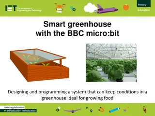
Building a Smart Greenhouse with Micro:Bit

Dive into the challenges of building and programming a smart greenhouse using a Micro:Bit. Learn to create circuits with LEDs, connect to a 9V battery, integrate a soil moisture sensor, and control a servo to water plants. Get hands-on experience in wiring and programming for a sustainable gardening solution.

Download Presentation

Please find below an Image/Link to download the presentation.
The content on the website is provided AS IS for your information and personal use only. It may not be sold, licensed, or shared on other websites without obtaining consent from the author.If you encounter any issues during the download, it is possible that the publisher has removed the file from their server.
You are allowed to download the files provided on this website for personal or commercial use, subject to the condition that they are used lawfully. All files are the property of their respective owners.
The content on the website is provided AS IS for your information and personal use only. It may not be sold, licensed, or shared on other websites without obtaining consent from the author.
E N D
Presentation Transcript
Breadboards and 3-Pin Components
Wiring and Programming a Smart Greenhouse This week we shall work through the challenges to produce our own smart greenhouses controlled by a Micro:Bit.
BRONZE Challenge: Step 1. We need a red LED showing when the power is on. So, using a breadboard, recreate this circuit: 1 2 3 3V GND BBC Micro:Bit 1 k
BRONZE Challenge: Step 2. Our plants need light. So we need to create a circuit where we can have a white LED shine when it s dark. 0 1 2 3V GND BBC Micro:Bit 1 k 1 k Hint: You will need to program the Micro:Bit. If light level < 50, digital write P0 to HIGH.
SILVER Challenge: Step 3. As we want to add more components, 3V will no longer be enough power. So we need to upgrade to a 9V battery: 0 1 2 3V GND BBC Micro:Bit 1 k 1 k +9V Hint: There is an example for this on the next slide.
Adding a Battery: Here is an example of how to connect both a Micro:Bit and a battery to a breadboard:
SILVER Challenge: Step 4. Now we want to connect a soil moisture sensor to the circuit. This needs to be off the breadboard so it can be inserted into a plant pot. 0 1 2 3V GND Power Control Ground BBC Micro:Bit 1 k 1 k +9V
SILVER Challenge: Step 5. Now program the Micro:Bit so if the soil is dry, a sun symbol appears on the screen. If the soil is damp, a raindrop symbol appears on the screen. Hint: If read analog pin P1 < 75 then show sun symbol, else show raindrop symbol.
GOLD Challenge: Step 6: We now need a servo connected to the breadboard and pin 2 of the Micro:Bit. This servo is turning a tap to release water when the soil is dry. To turn on the tap the servo needs to rotate 90 . To turn off, it needs to rotate back to 0 .
Congratulations! You have now built and programmed a Micro:Bit controlled greenhouse!
New Component: Using the Micro:Bit with breakout board (as shown below), we can access more of the Micro:Bit s pins. This increases the number of programmable pins in TinkerCAD to 10.
Extension Challenge: Using the Micro:Bit breakout board, a breadboard, 3 LEDs, resistor(s), a 9V battery, and a piezo (a type of buzzer), create a traffic light system which beeps when it is safe for pedestrians to cross. Piezo Buzzer Buzzer Symbol Remember: The traffic light sequence is: Red, red and amber, green, amber, repeat.
Extension Challenge: Can you now draw the circuit diagram for you traffic light system? Send a photo of your drawing to crastaff@aber.ac.uk once completed.