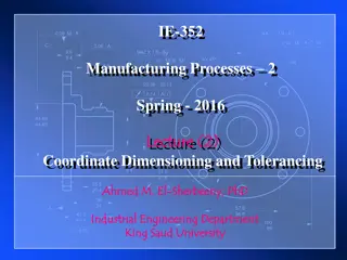
Calculation of Shaft Diameter for Pulley and Gear Assembly
A detailed analysis is conducted to determine the shaft diameter required for a system consisting of a pulley and a gear on a steel shaft. Reactions, load diagrams, critical section identification, and stress distribution are assessed to calculate the dimensions effectively based on the applied forces and material properties.

Download Presentation

Please find below an Image/Link to download the presentation.
The content on the website is provided AS IS for your information and personal use only. It may not be sold, licensed, or shared on other websites without obtaining consent from the author.If you encounter any issues during the download, it is possible that the publisher has removed the file from their server.
You are allowed to download the files provided on this website for personal or commercial use, subject to the condition that they are used lawfully. All files are the property of their respective owners.
The content on the website is provided AS IS for your information and personal use only. It may not be sold, licensed, or shared on other websites without obtaining consent from the author.
E N D
Presentation Transcript
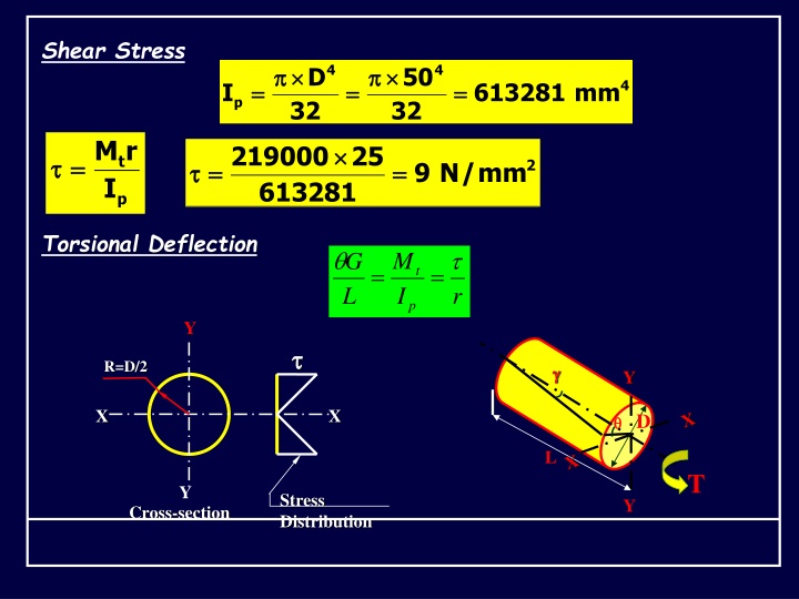
Shear Stress 4 4 D 50 4 = = = = = = I 613281 mm p 32 32 M r 219000 25 = = t 2 = = = = 9 N / mm I 613281 p Torsional Deflection M G = = t L I r p Y R=D/2 Y X X D L T Y Stress Distribution Y Cross-section
M L = = t GI p 219000 450 = = = = 0 0016 . rad 4 9 95 . 10 613281 I p 360 = = = = = = 0 0061 . rad 0 0061 . 0 0925 . deg ree 2
Example No.2 A pulley of diameter 750 mm and a gear of 280 mm diameter are mounted on a steel shaft. The belt pulls on the pulley with 1670 N and 1330 N at 450. The gear tooth force is 900 N . The allowable shear stress and tensile stress for the shaft material are 57 N/mm2and 71 N/mm2respectively. Determine the shaft diameter. 1670 N 450 A B 1330 N 900 N 375 375 500
Reactions -Pulling forces of the belt should be resolved in the vertical and horizontal directions. i.e., Fv: Vertical tension component. Fh: Horizontal tension component. Fv = Fh = (1670+1330)sin 450 = 3000 sin 45 =2120 N
Vertical Reactions From Equilibrium: 2120 N 900 N A B M @ B : 375 375 500 RA (375+375+500) = (900 500)+2120 (375+500) 1250 RA= 450000+ 1855000 = 2305000 M @ A : RB RA RA = 1844 N RB (375+375+500) = 900 (375+375)+2120 375 1250 RB= 675000 + 795000 RB = 1176 N CKECK : FY= 0 : RA+ RB= 1844+1176 = 2120 + 900 = 3020 Vertical reactions are right.
Horizontal Reactions From Equilibrium: 2120 N A B M @ B : 375 375 500 HA (375+375+500) = 2120 (375+500) 1250 HA= 1855000 HA = 1484 N HB HA M @ A : HB (375+375+500) = 2120 375 1250 HB= 795000 HB = 636 N CKECK : FY= 0 Horizontal reactions are right. :HA+ HB= 1484 + 636 = 2120
Load Diagrams Vertical Horizontal 2120 N C 900 N 2120 N D B A B A 375 375 500 375 375 500 1844 N 1176 N 1484 N 636 N 1844 N 1484 + + S.F.D. _ 636 276 1176 B.M.D. + + 556.5 588 N.m 619 127.5 N.m MT.D. T =127.5 N.m
Critical Section Section at C is the critical one This section loaded by: 1.Shear force Qx=1484 N & Qy=1844 N (Neglected values) 2. Bending Moment Mx=556.5 N.m & My=619 N.m 3. Torque Mt= 127.5 N.m
Shaft Design 1. Design Based on Bending Moment Mx=556.5 N.m My=619 N.m 2 y x b equiv 2 = = + + M M ( ) M ( ) Mb= = 832 N m . 2 2 = = + + M 556 ( 5 . ) 619 ( ) b equiv But, all = 71 N/mm2 (given) 3 8 32 10 D 2 832000 32 = = = = b 4 3 D D M Y bx 64 = = b I 832000 32 x = = 71 3 D 832000 32 = = = = D 49 22 . mm 3 71 = = D 50 mm
Shaft Design 2. Design Based on twisting Moment Mt=127.5 N.m And, all = 57 N/mm2 (given) 3 127 5 . 10 D 2 M r = = 4 D = = t 32 I 127500 16 p = = 57 3 D 127500 16 = = = = D 22 49 . mm 3 57 = = D 23 mm
Shaft Design 3. Design Based on twisting & bending Moments Mt=127.5 N.m Mx=556.5 N.m My=619 N.m Design will be carried out according to one of the theories of elastic failure. (i.e., Maximum shear or maximum principle stress theory).