Campus Network Design & Operations Workshop: Layer 1, 2, and 3 Refresher
Enhance your understanding of core networking concepts with this refresher workshop on Layer 1, 2, and 3 in campus network design and operations. Explore topics like physical characteristics, equipment types, building networks, data link organization, and practical examples. Get a clear grasp of key terminology and networking essentials. Materials under Creative Commons license. Last updated on December 10, 2018.

Download Presentation

Please find below an Image/Link to download the presentation.
The content on the website is provided AS IS for your information and personal use only. It may not be sold, licensed, or shared on other websites without obtaining consent from the author. If you encounter any issues during the download, it is possible that the publisher has removed the file from their server.
You are allowed to download the files provided on this website for personal or commercial use, subject to the condition that they are used lawfully. All files are the property of their respective owners.
The content on the website is provided AS IS for your information and personal use only. It may not be sold, licensed, or shared on other websites without obtaining consent from the author.
E N D
Presentation Transcript
Layer 1, 2 and 3 Refresher Campus Network Design & Operations Workshop These materials are licensed under the Creative Commons Attribution-NonCommercial 4.0 International license (http://creativecommons.org/licenses/by-nc/4.0/) Last updated 10th December 2018
Objectives To revise core networking concepts To ensure we are using the same terminology
What is this? 7 Application 6 Presentation 5 Session 4 Transport 3 Network 2 Link 1 Physical
Layer 1: Physical Layer Transfers a stream of bits Defines physical characteristics Connectors, pinouts Cable types, voltages, modulation Fibre types, lambdas Transmission rate (bps) No knowledge of bytes or frames 101101
Types of equipment Layer 1: Hub, Repeater, SFP, Media Converter Hubs are not used any more! Works at the level of individual bits All data sent out of all ports Hence data may end up where it is not needed Transmission errors can occur BER (Bit Error Rate), SNR (Signal to Noise Ratio)
Building networks at Layer 1 What limits do we hit? Cat5E/Cat6A cable length? Fibre length? Fibre type? Media converters? copper fibre Media Converter Media Converter
Layer 2: (Data) Link Layer Organises data into frames May detect transmission errors (corrupt frames) May support shared media Addressing (unicast, multicast) who should receive this frame Access control, collision detection Usually identifies the L3 protocol carried
Example Layer 2: PPP Information Flag Protocol CRC Flag Also includes link setup and negotiation Agree link parameters (LCP) Authentication (PAP/CHAP) Layer 3 settings (IPCP)
Example Layer 2: Ethernet Header Dest MAC Src MAC Proto Information CRC Gap Preamble MAC addresses Protocol: 2 bytes e.g. 0800 = IPv4, 0806 = ARP, 86DD = IPv6 Preamble: carrier sense, collision detection
Types of equipment (contd) Layer 2: Switch, Bridge Receives whole layer 2 frames and selectively retransmits them Learns which MAC address is on which port If it knows the destination MAC address, will send it out only on that port Otherwise, it sends it out on all ports Broadcast frames must be sent out of all ports, just like a hub Doesn t look any further than L2 header
Address Learning MAC addresses learned by each switch S1 MAC Port A 1 B 1 C 2 D 2 S2 MAC Port A 1 B 2 C 3 D 3 S1 1 2 3 3 S2 S3 1 2 1 2 S3 MAC C D A B Port 1 2 3 3 B A C D
How Address Learning Works After receiving a frame with the source MAC address X on port Y, it learns that X is connected to port Y Learned MAC address and the corresponding port are added to the MAC Address Table ("bridge forwarding table") Later, when it receives a frame with destination MAC address = X, it can send it out only on port Y, and not on other ports If the destination MAC address of a received frame is not in the MAC Address Table, it must be sent out on all ports (like a hub)
Address Learning (contd) If a switch port is connected to a single computer, then only its Ethernet address will be associated with that port If a switch port is connected to another switch (or hub or AP), then a number of Ethernet addresses may be associated with that port Entries in the forwarding table may expire, or be forced out if it runs out of space A managed switch will let you inspect its forwarding table
Building networks at Layer 2 What limits do we hit? Why can't we just keep adding more and more switches and devices indefinitely? What problems occur? Switch Switch Switch
Layer 3: (Inter)Network Layer Connects Layer 2 networks together Forwarding data from one network to another These different networks are called subnets (short for sub-network) Universal datagram (Layer 3 data unit) format Unified addressing scheme Independent of the underlying L2 network(s) Addresses organised so that it can scale globally (aggregation) Identifies the layer 4 protocol being carried Fragmentation and reassembly
Example Layer 3: IPv4 Datagram Header hdr csum Version, length, flags, fragments TTL Dest IP Src IP Proto Information Src, Dest: IPv4 addresses Protocol: 1 byte e.g. 6 = TCP, 17 = UDP (see /etc/protocols)
Types of equipment (contd) Layer 3: Router Looks at the destination IP in its Forwarding Table to decide where to send next Collection of routers managed together is called an Autonomous System The forwarding table can be built by hand (static routes) or dynamically Within an AS: IGP (e.g. OSPF, IS-IS) Between ASes: EGP (e.g. BGP)
Traffic Domains Router Switch Switch Switch Switch Switch AP Collision Domain: where several devices share one communication medium (e.g. wireless networks) Broadcast Domain Broadcast Domain: all devices on the same sub-network
Network design guidelines No more than ~250 hosts on one subnet Implies: subnets no larger than an IPv4 /24 Maybe bigger if a lot of address churn (e.g. roaming wireless devices) Campus guideline At least one subnet per building More than one subnet will usually be required for larger buildings Wireless many APs, each covering a small area, are better than one AP covering a large area neighboring APs should be on non-overlapping radio channels
Layer 4: Transport Layer Identifies the endpoint process Another level of addressing (port number) May provide reliable delivery Streams of unlimited size Error correction and retransmission In-sequence delivery Flow control Might just be unreliable datagram transport
Example Layer 4: UDP Header Src Port Dst Port Len Checksum Information Port numbers: 16 bits each Well-known ports: e.g. 53 = DNS Ephemeral ports: 1024, chosen dynamically by client
Example Layer 4: TCP Header Src Port Dst Port Information Seq Ack Flag Win Chk Urg Port numbers: 16 bits each Well-known ports: e.g. 80 = HTTP Ephemeral ports: 1024, chosen dynamically by client Reliable transmission: Sequence and Acknowledgement numbers Flow control: Window Session flags including SYN, ACK, FIN, RST Extensible via Options
Layers 5 and 6 Session Layer: long-lived sessions Re-establish transport connection if it fails Multiplex data across multiple transport connections Presentation Layer: data reformatting Character set translation Neither exist in the TCP/IP suite: the application is responsible for these functions
Layer 7: Application layer The actual work you want to do Protocols specific to each application Give some examples
OSI vs TCP/IP Source: William Stallings Data and Computer Communications
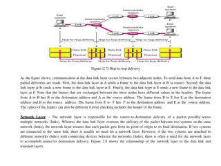
Encapsulation Each layer provides services to the layer above Each layer makes use of the layer below Data from one layer is encapsulated in frames of the layer below
Encapsulation in action L2 hdr L3 hdr L4 hdr Application data L4 segment contains part of stream of application protocol L3 datagram contains L4 segment L2 frame has L3 datagram in data portion
For discussion Can you give examples of equipment which interconnects two networks and operates at layer 4? At layer 7? At what layer does a wireless access point work? What is a Layer 3 switch ? How does traceroute find out the routers which a packet traverses?
Debugging Tools What tools can you use to debug your network At layer 1? At layer 2? At layer 3? Higher layers?


 Link Layer")


")


")

Network Layer")

")