Canal and Cross Drainage Works Overview
Explore the design, construction, and maintenance of canal and cross drainage works, including types of canals, canal lining standards, safety parameters, and more. Learn about the classifications, functions, alignment, and sources of canals to understand their significance in water conveyance and irrigation. Discover the different types of canals based on natural supply sources, functions, financial output, discharge, and canal alignment.

Download Presentation

Please find below an Image/Link to download the presentation.
The content on the website is provided AS IS for your information and personal use only. It may not be sold, licensed, or shared on other websites without obtaining consent from the author.If you encounter any issues during the download, it is possible that the publisher has removed the file from their server.
You are allowed to download the files provided on this website for personal or commercial use, subject to the condition that they are used lawfully. All files are the property of their respective owners.
The content on the website is provided AS IS for your information and personal use only. It may not be sold, licensed, or shared on other websites without obtaining consent from the author.
E N D
Presentation Transcript
Canal and Cross Drainage Works
Table of contents Cross Drainage Works Recommendations Design of Cross Drainage Works Construction of Cross Drainage Works Guidelines for Cross Drainage Works 4 1 Basics Of Canals Canal Types Of Canal 5 Canal Lining & respective Indian Standards 2 Operation of Cross Drainage Works Maintenance of Cross Drainage Works Types of Lining on Canal Indian Standards to be Used in Different Canal Lining 3 6 Cross Drainage Work Safety Parameters Cross Drainage Works Definition & Types Safety of Cross Drainage Work 2
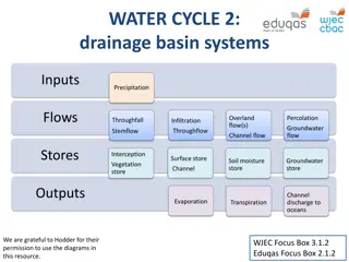
Canals An artificial open channel carrying water including situations passing through tunnels enroute. IS 4410 (Part 5) : 2023. Canals are manmade waterways channels, for water conveyance. They help in irrigation, water control and flood prevention. The canal comprises of earth work, concrete, lining, head regulators and expansive joints. 3
Types of Canals Classification based on Natural Supply of source Classification based on Functions Classification based on Type of Boundary of surface soil Classification based on Financial Output Classification based on Discharge Classification based on Canal Alignment 4
Types of Canals Based on Natural Supply Sources Based on Functions Permanent Canal Inundation Canal Carrier Canal Feeder Canal Navigational Canal Irrigation Canal Power Canal 5
Types of Canals Based on Financial Output Protective Canal Productive Canal Based on Canal Alignment Based on Type of Boundary of surface soil Contour Canal Alluvial Canal Non-Alluvial Canal Canal Ridge Rigid Canal Side Slope Canal 6
Types of Canals Based on Discharge Major Distributary Canal Minor Field Canal Distributary Canal Main Canal Branch Canal The principal channel of a canal system off-taking from a river or a reservoir or a feeder and also called as Main Line . A canal receiving its supply from the main canal and acting as feeder for distributarie s. It is also called Lateral A channel receiving its supply from main or the branch canal. It supplies water to minors and watercourses. It will be called a Major Distributary The channel that conveys water from water courses to the cultivator s fields. It supplies water to another distributary called a Minor Distributary. These Definitions are Taken From IS 4410 (Part 5) : 2023. 7
Indian Standards to be Used In Canal Lining The Following Codes are Used in canal lining, Maintenance, etc. S. No. Criteria for design of lined canals and guidance for selection of type of lining (First Revision) 2 IS 10646 : 1991 Canal linings Cement concrete tiles - Specification (First Revision) 3 IS 11809 : 1994 Lining for canals by stone masonry - Code of practice (First Revision) 4 IS 12379 : 1988 Code of practice for lining of water - Courses and field channels 5 IS 13143 : 1991 Joints in concrete lining of canals - Sealing compound - Specification 6 IS 3872 : 2002 Lining of canals with burnt clay tiles - Code of practice (First Revision) Laying .cement concrete/stone slab lining on canals - Code of practice (Second Revision) 8 IS 4515 : 2002 Stone pitched lining for canals - Code of practice (Second Revision) 9 IS 4558 : 1995 Under - Drainage of lined canals - Code of practice (Second Revision) 10 IS 4701 : 1982 Code of practice for earthwork on canals (First Revision IS 4839 (Part 1) : 1992 Revision) IS Number IS Title Cement Concrete Shotcrete Lining 1 IS 10430 : 2000 Asphalti c Lining Hard Surface Type Lining Pre Cast Concrete Lining Stone Block Lining 7 IS 3873 : 1993 Cement Mortar Lining Brick Lining Maintenance of canals code of practice: Part 1 unlined canals (Second 11 8
Indian Standards to be Used In Canal Lining S. No. 12 IS Number IS Title IS 4839 (Part 2) : 1992 Maintenance of canals - Codb of practice: Part 2 lined canals (Second Revision) Code of practice for maintenance of canals: Part 3 canal structures, drains, outlets, jungle, clearance, plantation and regulation second revision) Sealing expansion joints in concrete lining of canals - Code of practice (First Revision) Guide for laying combination lining for existing unlined canals (First Revision) Guide for planning and layout of canal system for irrigation (First Revision) Guide for location, selection and hydraulic design of canal escapes (First Revision) Criteria for design of cross - section for unlined canals in alluvial soil (First Revision) Soil - Cement lining for canals - Code of practice (First Revision) Lining of canals with polyethylene film - Code of practice (First Revision) Assessment of Seepage Losses in Canals by Analytical method- Guidelines ( first revision) Subsurface exploration for canals and cross drainage works - Code of practice (First Revision) 13 IS 4839 (Part 3) : 1992 14 IS 5256 : 1992 15 16 17 18 19 20 IS 5690 : 1982 IS 5968 : 1987 IS 6936 : 1992 IS 7112 : 2002 IS 7113 : 2003 IS 9698 : 1995 21 IS 9447 : 2023 22 IS 11385 : 2008 9
IS 10430 : 2000 Criteria for design of lined canals and guidance for selection of type of lining (First Revision) Seepage Control - Canal reaches of sufficient length having permeability of 1x 10⁻⁶ (cm/s) or less need not be lined when the velocity in the canal does not exceed the permissible velocity. However, reaches of permeability 1x 10⁻⁶ (cm/s) or less may be lined, particularly in power channels, for hydraulic efficiency and erosion resistance. Canal reaches of greater permeability may be lined with suitable material. Strength and Durability - The canal lining shall be able to withstand the effect of velocity of water, rain, sunshine, frost, freezing and thawing (where applicable), temperature and moisture changes, chemical action of salts, etc. With suitable treatment, lining should be able to withstand the effect of gypsum, black cotton soil/bentonite. It should also be able to withstand the damaging effect caused by abrasions, cattle traffic, rodents and weed growth. Side Slopes - Lining is usually made to rest on stable slopes of the natural soil; so slopes should be such that no earth pressure or any other external pressure is exerted over the back of the lining. Sudden drawdown of water level in the lined canal should be controlled by strict operation rules and regulations to avoid external pressure on the lining. 10
IS 10430 : 2000 Criteria for design of lined canals and guidance for selection of type of lining (First Revision) Berm - In deep cut reaches of canals with discharge capacity exceeding 10 cumecs, it is desirable to provide berms of 3 to 5 m width on each side for stability, facility of maintenance, silt clearance. Dowla - To check the ingress of rain water behind the lining of the side slopes of the canals, horizontal cement concrete coping 100 mm to 150 mm thick, depending upon size of canal should be provided at the top of lining. The width of coping at the top shall not be less than 225 mm for discharge up to 3 cumecs, 350 mm for discharge more than 3 cumecs and 550 mm for discharge more than 10 cumecs. Limiting Velocities of lining are given below: a) Stone-pitched lining -1.5 m/sec b) Burnt clay tile or brick lining -1.8 m/sec c) Cement concrete lining- 2.7 m/sec 11
IS 10646 : 1991 Canal linings - Cement Concrete Tiles - Specification DIMENSIONS -The nominal dimension shall be as below: 500 mm x 500 mm, 500 mm x 250 mm, 400 mm x 400 mm, 300 mm x 300 mm and 250 mm x 250 mm. TOLERANCE Tolerance in Length and breadth shall be of 3 mm and in thickness shall not be less than the specified value. FLEXURAL STRENGTH OF MANUFACTURED TILES When tested according to the method given at Annex A, minimum breaking load per cm length of tile shall not be less than 41 kg for 60 mm, 29 kg for 50 mm and 18 kg for 40 mm tiles thickness. 12
IS 10646 : 1991 Canal Linings - Cement Concrete Tiles - Specification Test - The specimen shall be immersed in potable water for 24 hours and then taken out and wiped dry. The specimen shall be placed horizontally on roller bearers 1.50 mm apart with their length parallel to bearers. The load shall be applied at mid-stand by means of steel bar parallel to the bearers. The length of the bearers and that of the loading bar shall be longer than the length of the specimen and their contact shall be rounded to a diameter- of 25 mm. A plywood packing 3 mm thick and 25 mm wide shall be placed between the specimen. Loading - Starting from zero, the load shall be increased steadily and uniformly at a rate not exceeding 2 kg/cm length per minute up to the load. 13
IS 11809 : 1994 Lining for canals by stone masonry - Code of practice (First Revision) Dimensions of Stones and Thickness of Lining ( Clause 4.1 ) Sr.No Canal Capacity (Cumec) Thickness Of Lining(mm) Average Dimension(mm) Minimum Dimension(m m) 75 110 150 1. 2. 3. 0 to less than 10 10 to less than 100 100 above 150 225 300 150 225 300 The stone should be laid on lime mortar ( 1 : 2 ) or cement mortar 1 : 3 over a bed of minimum 12 mm thick lime/cement mortar. 14
IS 11809 : 1994 Lining for canals by stone masonry - Code of practice (First Revision) The stone should be laid on lime mortar ( 1 : 2 ) or cement mortar 1 : 3 over a bed of minimum 12 mm thick lime/cement mortar. The lining should be started after at least 35 m length of canal sub-grade is properly dressed to receive lining. The subgrade should be uniformly soaked with water, without making it slushy, to ensure that water penetrates to a depth of about 300 mm in sandy soil and about 150 mm in other soils. 15
Cross Drainage Work In an Irrigation project, when the network of main canals, branch canals, distributaries, etc. are provided, then these canals may have to cross the natural drainages like rivers, streams, nallahs, etc. at different points within the command area of the project. The crossing of the canals with such obstacle cannot be avoided. So, suitable structures must be constructed at the crossing point for the easy flow of water of the canal and drainage in the respective directions. These structures are known as cross-drainage works. Works required to construct, to cross the drainage are called Cross Drainage Works (CDWs). At the meeting point of canals and drainages, bed levels may not be same. Depending on their bed levels, different structures are constructed and accordingly they are designated by different names. 16
Types of Cross Drainage Work Type I (Irrigation canal passes over the drainage) (a) Aqueduct (b) Siphon Aqueduct Type II (Drainage passes over the irrigation canal) (a) Super passage (b) Siphon super passage Type III (Drainage and canal intersection each other of the same level) (a) Level crossing (b) Inlet and outlet 17
AQUEDUCT Aqueduct - The hydraulic structure in which the irrigation canal is taken over the drainage (such as river, stream etc.) is known as aqueduct. This structure is suitable when bed level of canal is above the highest flood level of drainage. In this case, the drainage water passes clearly below the canal. 18
Siphon Aqueduct Siphon Aqueduct - In a hydraulic structure where the canal is taken over the drainage, but the drainage water cannot pass clearly below the canal. It flows under siphonic action. So, it is known as siphon aqueduct. This structure is suitable when the bed level of canal is below the highest flood level. 19
Super Passage The hydraulic structure in which the drainage is taken over the irrigation canal is known as super passage. The structure is suitable when the bed level of drainage is above the full supply level of the canal. The water of the canal passes clearly below the drainage. 20
Siphon Super Passage The hydraulic structure in which the drainage is taken over the irrigation canal, but the canal water passes below the drainage under siphonic action is known as siphon super passage. This structure is suitable when the bed level of drainage is below the full supply level of the canal. 21
Level crossing When the bed level of canal and the stream are approximately the same and quality of water in canal and stream is not much different, the cross drainage work constructed is called level crossing where water of canal and stream is allowed to mix. With the help of regulators both in canal and stream, water is disposed through canal and stream in required quantity. Level crossing consists of following components (i) crest wall (ii) Stream regulator (iii) Canal regulator. 22
Design of Cross Drainage Work(IS 7784 (Part 1) : 2013) Data Requirement of Cross Drainage Work - A location map for the work with results of subsurface exploration conducted at site, cross-sections of the stream, upstream and downstream of the proposed site, should be prepared. A catchment area map to a suitable scale, with contour markings at suitable intervals showing the main drainage channel from its sources together with all its tributaries. Design Flood Design flood for drainage channel to be adopted for cross drainage works should depend upon the size of the canal, size of the drainage channel and location of the cross drainage. A very long canal, crossing a drainage channel in the initial reach, damage to which is likely to affect the canal supplies over a large area and for a long period, should be given proper weightage. A very long canal, crossing a drainage channel in the initial reach, damage to which is likely to affect the canal supplies over a large area and for a long period, should be given proper weightage. Cross drainage structures are divided into four categories depending upon the canal discharge and drainage discharge. Design flood to be adopted for these four categories of cross drainage structures would depend upon type of structure and flood frequency. The discharges determined by different methods mentioned in IS 5477 (Part 4) should be compared to see if any large variations are exhibited. 23
Design of Cross Drainage Work (IS 7784 (Part 1) : 2013) For working out tilt design of an aqueduct, the specific design data should be available in addition to those laid down by IS 7784 (Part 1) : 1993. Wing walls for drainage may be provided with 2 : 1and 3 : 1 splays on upstream and downstream side; the splay should not be flatter than 3 : 1 and 4 : 1 respectively. Canal transitions should preferably be provided with 2 : 1 and 3 : 1 splays on upstream and downstream side, but not flatter than 3 : 1 and 5 : 1 respectively. 24
Design of Cross Drainage Work (IS 7784 (Part 2/Sec 1) : 1995) The maximum spacing of joints in either direction should be limited to 20 m. A gap of 15 mm with water stops at all the joints across along the barrel should be provided to Accommodate the movements. A suitable arrangement for supporting the section of the aqueduct may be decided depending upon the nature of foundation, difference between HFL of the drain and bed of canal and height between bed of canal and bottom of stream/drain and the afflux allowable in the drain. 25
Design of Cross Drainage Work (IS 7784 (Part 2/Sec1) : 1995) Hydraulic design data shall be made available as given in IS 7784 (Part I). In the case of syphon super passage the following data shall also he made available in addition: 1) Side slopes, 2) Allowable head loss, 3) Whether canal is lined and if so the lining maternal. Bottom slab of the drainage bed should also be considered for H.F.L. loading due to water and loading due to surcharge of earth and partial silt load. 26
Design of Cross Drainage Work IS 7784 (Part-2/Sec 2): 2000 The section of the trough should permit a scouring velocity at maximum observed flood. A velocity of 2 to 3 m per second is normally permissible. Afflux should be such that it does not exceed the limits of submergence and tolerances of the environments. Energy loss should he determined in accordance with IS 7784 (Part 1). High flood level (H.F.L) calculated or observed, whichever is more at the center line of the crossing, water surface slope of the stream or drain and the total length of the work being known, the H.F.L at the upstream and downstream of the work can be determined, taking into consideration the parameters at the site. 27
Construction of Cross Drainage Work (IS 9913: 2000 ) Static penetration tests shall carried out at all important components of the proposed structure, that is abutment ,pier, wing wall. Where a ring bund or a coffer dam is to be formed, the top level should be kept well above the normal flood level as per provisions of IS 9795(Part 1). Where feasible the foundation concrete shall be laid in a single pour. 28
Construction of Cross Drainage Work (IS 9913: 2000 ) The outer diameter shall be large and preferably not less than 6 m with the minimum thickness of caisson wall, as one meter. Pile foundations are generally not provided in case of aqueducts Piles, where unavoidable, should not he provided within the flood zone of the river With deep scour. Piers and abutments may he solid, or cellular type The minimum thickness, of wall shall be 600 m The construction joint splash zone. 29
Operation of Cross Drainage Work The water-shed canals do not cross natural drainages. But in actual orientation of the canal network, this Operational condition may not be available and the obstacles like natural drainages may be present across the canal. So, the cross drainage works must be provided for running the irrigation system. At the crossing point, the water of the canal and the drainage get intermixed. So, for the smooth running of the canal with its design discharge the cross drainage works are required. The site condition of the crossing point may be such that without any suitable structure, the water of the canal and drainage can not be diverted to their natural directions. So, the cross drainage works must be provided to maintain their natural direction of flow. 30
Maintenance of Cross Drainage Work (IS 7331 : 1981) The approach and exit channels in the vicinity of cross drainage works shall be cleared of silt, debris, stumps, branches of trees, etc. before the onset of monsoon or the reopening of the channel after a closure, to keep the work free from obstructions. Any crack and hole in upstream and downstream floors of the cross drainage works shall be duly repaired well before the monsoon sets in. Any potholes or open joints in the masonry/concrete in the floor or side walls shall be properly repaired, Any deviation from the :original formations on the bed and sides is to be noticed. 31
Maintenance of Cross Drainage Work (IS 7331 : 1981) The drainage or, weep holes and pressure release valves in abutments, wings, etc. shall be cleaned of all extraneous matter to prevent building up of hydrostatic pressure, in excess of the designed provision. It shall be ensured that the water seals or the asphalt joints are in tact, Leakage through water seals whether in canal through, or in the drainage vents, shall be corrected as far as possible by the use of appropriate filler material. 32
Safety of Cross Drainage Work Cross drainage works, or CD works, are important for road safety and flood prevention. The safety of cross drainage works can be improved by: Using local materials Use materials that are available locally and design the shape and size of the cross drainage work to take advantage of their properties. Inspecting on-site Before deciding on the location of a cross drainage work, inspect the site to assess all relevant factors. IS 10386 (Part 9) : 1998 Safety code for operation and maintenance of river valley projects: Part 9 canals and cross drainage works 33
Safety of Cross Drainage Work Designing for a flood return cycle For rural roads, it's often better to design a cross drainage work for a flood return cycle of five to ten years. This can be considered a temporary structure, and data collected during its life can help design a more adequate structure in the future. Considering protection works Depending on the site conditions, protection works like retaining walls and stone pitching may be required. Designing the waterway The waterway should be designed so that the velocity generated during a dominant flood is enough to scour material, but not so excessive that it damages the work. 34
Write to Us wrd@bis.gov.in