CASE 752EX Vibratory Compactor Service Repair Manual Instant Download
CASE 752EX Vibratory Compactor Service Repair Manual Instant Download
Download Presentation

Please find below an Image/Link to download the presentation.
The content on the website is provided AS IS for your information and personal use only. It may not be sold, licensed, or shared on other websites without obtaining consent from the author. If you encounter any issues during the download, it is possible that the publisher has removed the file from their server.
You are allowed to download the files provided on this website for personal or commercial use, subject to the condition that they are used lawfully. All files are the property of their respective owners.
The content on the website is provided AS IS for your information and personal use only. It may not be sold, licensed, or shared on other websites without obtaining consent from the author.
E N D
Presentation Transcript
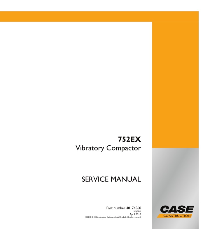
752EX Vibratory Compactor SERVICE MANUAL Part number 48174560 English April 2018 2018 CNH Construction Equipment (India) Pvt Ltd. All rights reserved.
Contents INTRODUCTION Machine completion and equipment.............................................. 05 [05.102] Machine completion................................................................ 05.1 Engine....................................................................................... 10 [10.001] Engine and crankcase ............................................................. 10.1 [10.202] Air cleaners and lines .............................................................. 10.2 [10.254] Intake and exhaust manifolds and muffler ......................................... 10.3 [10.400] Engine cooling system ............................................................. 10.4 [10.310] Aftercooler.......................................................................... 10.5 [10.216] Fuel tanks .......................................................................... 10.6 Hydrostatic drive......................................................................... 29 [29.218] Pump and motor components...................................................... 29.1 Hydraulic systems....................................................................... 35 [35.000] Hydraulic systems.................................................................. 35.1 [35.300] Reservoir, cooler, and filters........................................................ 35.2 Frames and ballasting................................................................. 39 [39.100] Frame .............................................................................. 39.1 [39.500] Vibratory roller...................................................................... 39.2 Steering..................................................................................... 41 [41.101] Steering control .................................................................... 41.1 [41.200] Hydraulic control components...................................................... 41.2 [41.206] Pump............................................................................... 41.3 [41.216] Cylinders ........................................................................... 41.4 Electrical systems....................................................................... 55 [55.000] Electrical system ................................................................... 55.1 [55.100] Harnesses and connectors......................................................... 55.2 48174560 20/04/2018
[55.201] Engine starting system............................................................. 55.3 [55.301] Alternator........................................................................... 55.4 [55.302] Battery.............................................................................. 55.5 Platform, cab, bodywork, and decals............................................. 90 [90.AAA] Platform, cab, bodywork, and decals generic sub-group.......................... 90.1 48174560 20/04/2018
https://www.ebooklibonline.com Hello dear friend! Thank you very much for reading. Enter the link into your browser. The full manual is available for immediate download. https://www.ebooklibonline.com
INTRODUCTION 48174560 20/04/2018 1
INTRODUCTION Safety rules Personal safety This is the safety alert symbol. It is used to alert you to potential personal injury hazards. Obey all safety messages that follow this symbol to avoid possible death or injury. Throughout this manual you will find the signal words DANGER, WARNING, and CAUTION followed by special in- structions. These precautions are intended for the personal safety of you and those working with you. Read and understand all the safety messages in this manual before you operate or service the machine. DANGER indicates a hazardous situation that, if not avoided, will result in death or serious injury. WARNING indicates a hazardous situation that, if not avoided, could result in death or serious injury. CAUTION indicates a hazardous situation that, if not avoided, could result in minor or moderate injury. FAILURE TO FOLLOW DANGER, WARNING, AND CAUTION MESSAGES COULD RESULT IN DEATH OR SERIOUS INJURY. Machine safety NOTICE: Notice indicates a situation that, if not avoided, could result in machine or property damage. Throughout this manual you will find the signal word Notice followed by special instructions to prevent machine or property damage. The word Notice is used to address practices not related to personal safety. Information NOTE: Note indicates additional information that clarifies steps, procedures, or other information in this manual. Throughout this manual you will find the word Note followed by additional information about a step, procedure, or other information in the manual. The word Note is not intended to address personal safety or property damage. 48174560 20/04/2018 4
INTRODUCTION Safety rules Carefully read the safety rules contained herein and follow advised precautions to avoid potential hazards and to safeguard your safety and personal integrity. Your safety and that of the people around you depends on you. It is essential that you understand this manual for a correct inspection, lubrication and repair of this machine. Read this manual carefully and check that: You understand fully the symbols on the controls and the safety signs used in this manual and on the machine. You understand fully the speed, stability, braking and steering characteristics of the machine. If you are in any doubt, consult your Dealer. The safety messages in this section concern situations which may arise during normal machine operation, servicing and repair. These safety messages also indicate the different ways of coping with these situations. Other safety messages are used throughout the manual to indicate specific dangers. The information given in this chapter is a summary of the basic rules to respect at all times and does not exempt you from observing traffic regulations or the requirements of insurance companies. The presence of grease, oil, mud or (in winter) ice on the steps and access handles can cause accidents. Make sure they are always clean. When mounting or dismounting from the machine always face the machine and use the steps and access handles on the left-hand side of the machine. 1 LELI12TLB0048AB Wear close fitting clothing and safety equipment appropriate for the job: Safety helmet Safety shoes Heavy gloves Reflective clothing Wet weather clothing If the environment conditions make it necessary, the following personal safety equipment should be at hand: Respirators (or dustproof masks) Ear plugs or acoustic ears protections Goggles with lateral shield or masks for eyes protection 2 LELI12TLB0049AB Do not wear rings, wristwatches, jewels, unbuttoned or flapping clothing such as ties, torn clothes, scarves, open jacketsorshirtswithopenzipswhichcouldgetcaughtinto moving parts. Any functional disorders, especially those affecting the safety of the machine, should therefore be rectified im- mediately. 48174560 20/04/2018 5
INTRODUCTION Make sure that you fully understand the symbols of the safety decals applied on the machine. Make sure that they are always clean and perfectly legible. Be prepared for emergencies. Always keep a first aid kit and a fire extinguisher close at hand on the machine. Make sure that the fire extinguisher is serviced in accor- dance with the manufacturer s instructions. 3 LELI12TLB0050AB 48174560 20/04/2018 6
INTRODUCTION Product identification 1 PTIL17COM0094GB Hydraulic oil filters Vibration pump Travel pump Engine Articulation Joint Front roller drum Front travel motor Scraper Sprinkler tube Front exciter shaft Front roller frame Elastic suspension Front tank Steering cylinder Hydraulic oil cooler Steering unit Radiator Vibration motor Operators seat Steering pump Rear tank Battery Rear exciter shaft Rear travel motor Rear chassis Rear roller drum 1. 2. 3. 4. 5. 6. 7. 8. 9. 10. 11. 12. 13. 14. 15. 16. 17. 18. 19. 20. 21. 22. 23. 24. 25. 26. 48174560 20/04/2018 17
SERVICE MANUAL Engine 752EX 48174560 20/04/2018 10
Engine - Engine and crankcase Engine - Torque 1 PTIL18COM0016GB Bolt 1 2 3 Torque value 130 135 N m 115 125 N m 110 120 N m 48174560 20/04/2018 10.1 [10.001] / 3
Engine - Engine and crankcase Engine and crankcase - Service instruction The S8000 series of engine is a vertical, water cooled, direct Injection, with rotary pump compression ignition, 4 cylinder engine. The standard direction of rotation is anti-clockwise when looking from the flywheel end. Cylinders are numbered ascending from the radiator end, with first cylinder being nearest to the cooling fan. The engine has an integral block and crank case for rigidity and a single piece cylinder head unit covering all cylinders, with replaceable valve seat inserts. Each cylinder has two valves, one inlet and one exhaust. The valve nearest to the cooling fan is the exhaust valve fol- lowed inlet valve. This sequence of valves continues uniformly for all cylinders 48174560 20/04/2018 10.1 [10.001] / 4
Engine - Engine and crankcase Engine and crankcase - Remove 1. Remove the hood, see the Engine shields, hood latches, and trims - Remove - Hood Removal (90.102). 2. Remove the cooling pack. See the Engine cooling system - Remove - Cooling pack (10.400). 3. Loosenandremovethethermostatmountinghosecon- nections and cap the openings. 4. Swing the hoses clear of the engine (1). 5. Disconnect the alternator connections. See the Alter- nator - Remove (55.301). 6. Disconnect the engine oil pressure sensor connection. 7. Loosen the clamp and remove the silencer assembly. See the Exhaust pipes - Remove (10.254) 8. All the hydraulic and oil connector openings to be cov- ered properly to avoid entry of dust. 9. Disconnect the clog indicator connection and remove the air filter assembly with housing and pipes to intake manifold. See the Air pre-cleaner - Exploded view (10.202) 10. Disconnect all the starter connections. See the En- gine starter - Remove (55.201) . 11. Remove the travel and vibration pumps. Pump - Remove - Travel pump (29.218). See the 12. Lift the pump and set it aside. 13. Remove the hydraulic filter assembly. 14. Loosen the bolts (2) and remove the adapter (1) from the engine bell housing. 1 PTIL16TLB0324AB 48174560 20/04/2018 10.1 [10.001] / 5
Engine - Engine and crankcase 15. Loosen the bolts (2) and remove the coupling (1) from the flywheel. 2 PTIL16TLB0325AB 16. Disconnectthehydrauliclines(1)atthesteeringpump end and cap the openings. Set the hose aside. 3 PTIL14COM1364AB 17. Disconnect the fuel hoses from the fuel tank to mud filter and cap them. 18. Disconnect the fuel hose from filter to engine and to mud filter and cap them. 19. Disconnect the emergency stop switch. 20. Disconnect the throttle cable at the pump end and clear the cable from the engine. 21. Connect a suitable lifting device to the engine. 22. Loosen and remove the bolts (1) with washer (2). 23. Loosen and remove the bolts (3) with washer (4). NOTE: The bolt (5) is different from other bolts on the mounting bracket and has an additional alternator bracket spacer (6). Put an identification tag on the bolt and make sure to install the bolt in same location while mounting the engine. 4 PTIL18COM0019AA 48174560 20/04/2018 10.1 [10.001] / 6
Engine - Engine and crankcase 24. Lift the engine slowly. 25. Clear any cables or wires that may be in the way. 26. Lift the engine clear of the machine and mount on a trolley or stand. 48174560 20/04/2018 10.1 [10.001] / 7
Engine - Engine and crankcase Engine and crankcase - Install 1 PTIL18COM0016GB 1. Place the engine on the machine by using suitable lift- ing device. 2. Tighten the mounting bolts (1) with washer (2) to a torque of 115 125 N m. 3. Tighten the mounting bolts (3) with washers (4) and (5) to a torque of 110 120 N m. 48174560 20/04/2018 10.1 [10.001] / 8
Engine - Engine and crankcase 4. Torque the mounting bolt (6) to 115 125 N m. NOTE: The mounting bolt (6) is different from other mount- ing bolts on the same bracket and has additional alternator bracket spacer (7). 2 PTIL18COM0019AA NOTE: Apply anabond 121 E on bolts (2) and (4) threads from approximately middle of thread length up to end of thread length. Allow minimum 6 h of curing time before applying the dynamic load on bolts. Before applying anabond, clean the bolt and corresponding thread hole so that it should be free from oil and dirt. 5. Install the throttle cable at the pump end and install the cable to the engine. 6. Install the emergency stop switch. 7. Install the fuel hose from filter to engine and to mud filter. 8. Install the fuel hoses from the fuel tank to mud filter. 9. Clean the hose and connect the hydraulic lines (1) at the steering pump and cap opening. 3 PTIL14COM1364AB 10. Install the coupling (1) on to the flywheel. Install the washer and tighten the bolts (2) to a torque of 5 kgm. 4 PTIL16TLB0325AB 48174560 20/04/2018 10.1 [10.001] / 9
Engine - Engine and crankcase 11. Install the adapter (1) on to the engine bell housing and tighten the bolts (2) to a torque of 6.3 kgm. 5 PTIL16TLB0324AB 12. Install the hydraulic filter assembly. 13. Install the travel and vibration pumps. 14. Install all the starter connections. starter - Install (55.201) Refer Engine 15. Install the air filter assembly with housing and pipes to intake manifold and connect the clog indicator con- nection. 16. Remove the cover from hydraulic and oil connector openings assembly. 17. Install the silencer assembly and tighten the clamp. 18. Install the engine oil pressure sensor connection. 19. Install the alternator connections. Refer Alternator - Install (55.301) 20. Install the thermostat mounting hose connections and cap openings. 21. Install the cooling pack and hood. 48174560 20/04/2018 10.1 [10.001] / 10
Engine - Engine and crankcase Engine and crankcase - Disassemble - Top Engine 1. Disconnect the battery and store it in a dry place. 2. Remove the radiator fan. 3. Disconnect wiring from the alternator. 4. Remove fan belt. Discard if it is damaged. 5. Remove the alternator (1) from the engine. 1 PTIL16TLB0326AB 6. Drain out water from the radiator. NOTE: If coolant is used, collect it in a container and use again. 7. Drain the lubricating oil from the sump and discard the O-ring from the drain plug. 8. Disconnecttheradiatorfromtheengineanddiscardthe old hoses. 9. Disconnect the air cleaner and hose assembly from the bracket and inlet manifold. Discard the hose if it is cracked or damaged. 10. Disconnect the exhaust pipe from the exhaust flange. 11. Follow the procedure on turbocharger, 1. Disconnect the rubber hose (1) connecting the air cleaner to the turbocharger. 2. Disconnect the air delivery pipe with the heat shield from the turbocharger air outlet and air inlet mani- fold. 3. Disconnect the exhaust pipe (1) from the tur- bocharger expansion bellow flange and discard the joint. 4. Disconnect and remove the exhaust diffuser from the bracket. 2 PTIL16TLB0333AB 48174560 20/04/2018 10.1 [10.001] / 11
Suggest: If the above button click is invalid. Please download this document first, and then click the above link to download the complete manual. Thank you so much for reading
Engine - Engine and crankcase 5. Disconnect the lubrication oil inlet (1) and drain pipe from the turbocharger. 3 PTIL14COM1301AB 4 PTIL14COM1357AA 6. Disconnect the turbocharger from the exhaust man- ifold and discard the joint. 48174560 20/04/2018 10.1 [10.001] / 12
https://www.ebooklibonline.com Hello dear friend! Thank you very much for reading. Enter the link into your browser. The full manual is available for immediate download. https://www.ebooklibonline.com









![Comprehensive Case Study on [Insert Case Title Here]](/thumb/159705/comprehensive-case-study-on-insert-case-title-here.jpg)
