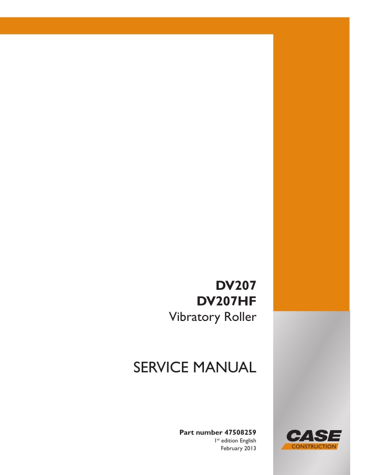
CASE DV207 Vibratory Roller Service Repair Manual Instant Download
CASE DV207 Vibratory Roller Service Repair Manual Instant Download
Download Presentation

Please find below an Image/Link to download the presentation.
The content on the website is provided AS IS for your information and personal use only. It may not be sold, licensed, or shared on other websites without obtaining consent from the author. If you encounter any issues during the download, it is possible that the publisher has removed the file from their server.
You are allowed to download the files provided on this website for personal or commercial use, subject to the condition that they are used lawfully. All files are the property of their respective owners.
The content on the website is provided AS IS for your information and personal use only. It may not be sold, licensed, or shared on other websites without obtaining consent from the author.
E N D
Presentation Transcript
DV207 DV207HF Vibratory Roller SERVICE MANUAL Printed in U.S.A. Part number 47508259 1st edition English Copyright 2013 CNH Europe Holding S.A. All Rights Reserved. Case is a registered trademark of CNH Europe Holding S.A. Boulevard Royal, 24 L-2449 Luxembourg. February 2013
QUICK REFERENCE CHAPTER GUIDE SECTION 00 MAINTENANCE GENERAL INSTRUCTIONS 1. Introduction 2. Safety precautions 3. Repair safety precautions 4. Product identifi cation 5. Check the tightening of bolted joints SECTION 00 MAINTENANCE GENERAL SPECIFICATIONS 6. Description of the machine 7. Tooling SECTION 10 ENGINE 8. Removing the engine 9. Removing the cooler SECTION 35 HYDRAULIC SYSTEM 10. Hydraulic system 11. Hydraulics SECTION 39 FRAMES 12. Articulated joint 13. Removing the hood SECTION 41 - STEERING 14. Steering cylinder SECTION 44 AXLES AND WHEELS 15. Removing the drum SECTION 50 CAB CLIMATE CONTROL 16. Removing the heater/cooling air fans SECTION 55 - ELECTRICAL SYSTEM 17. Electrical installation 18. Electrical system SECTION 90 CAB 19. Cab INDEX
TABLE OF CONTENTS Contents SECTION 00 MAINTENANCE GENERAL INSTRUCTIONS 1. Introduction .............................................................................................................................1-1 2. Safety precautions ..................................................................................................................2-1 2.1. 2.1.1. Precautionary statements personal safety signal words ................................................................................2-2 2.1.2. Machine safety and information signal words ...................................................................................................2-2 2.1.3. General safety rules ..........................................................................................................................................2-3 2.1.4. General operating safety ..................................................................................................................................2-4 2.2. Safety sign location overview ...........................................................................................................................2-5 2.2.1. Safety signs ......................................................................................................................................................2-6 2.3. General maintenance safety ...........................................................................................................................2-10 2.3.1. Fire and explosion prevention .........................................................................................................................2-10 2.3.2. Hazardous chemicals .....................................................................................................................................2-11 2.3.3. Battery safety ..................................................................................................................................................2-11 2.3.4. Air conditioning system ..................................................................................................................................2-12 2.3.5. Transportation safety ......................................................................................................................................2-12 2.3.6. Proper entry and exit ......................................................................................................................................2-12 2.3.7. Operator presence system .............................................................................................................................2-12 2.3.8. Operator protective structure ..........................................................................................................................2-13 2.3.9. Utility safety ....................................................................................................................................................2-13 2.4. Hand signals ...................................................................................................................................................2-14 Repair safety precautions ......................................................................................................3-1 Safety section ...................................................................................................................................................2-2 3. 3.1. 3.2. 3.3. Product identifi cation ..............................................................................................................4-1 Safety regulations .............................................................................................................................................3-2 Ecological measures & hygiene principles .......................................................................................................3-6 Fire measures ...................................................................................................................................................3-7 4. 4.1. Check the tightening of bolted joints ......................................................................................5-1 Summary of applications ..................................................................................................................................4-2 5. 5.1. Check the tightening of bolted joints .................................................................................................................5-2 SECTION 00 MAINTENANCE GENERAL SPECIFICATIONS 6. Description of the machine ....................................................................................................6-1 6.1. 6.2. 6.2.1. Engine oil ..........................................................................................................................................................6-3 6.2.2. Fuel ...................................................................................................................................................................6-4 6.2.3. Coolant .............................................................................................................................................................6-5 6.2.4. Hydraulic oil .....................................................................................................................................................6-5 6.2.5. Lube grease .....................................................................................................................................................6-5 6.2.6. Washer fl uid .....................................................................................................................................................6-5 6.2.7. Gear oil .............................................................................................................................................................6-5 6.2.8. Drum cooling liquid DV207HF ..........................................................................................................................6-6 6.3. Technical data DV207 / DV207HF ....................................................................................................................6-7 6.4. Dimensional diagram DV207 / DV207HF .........................................................................................................6-9 Machine construction ........................................................................................................................................6-2 Fluid/lubricant specifi cations .............................................................................................................................6-3 DV207 / DV207HF 1
https://www.ebooklibonline.com Hello dear friend! Thank you very much for reading. Enter the link into your browser. The full manual is available for immediate download. https://www.ebooklibonline.com
TABLE OF CONTENTS 7. Tooling .....................................................................................................................................7-1 7.1. Tooling and equipment ......................................................................................................................................7-2 SECTION 10 ENGINE 8. Removing the engine ..............................................................................................................8-1 9. Removing the cooler ...............................................................................................................9-1 SECTION 35 HYDRAULIC SYSTEM 10. Hydraulic system ...................................................................................................................10-1 Hydraulic diagram ...........................................................................................................................................10-3 11. Hydraulics ................................................................................................................................11-1 10.1. 11.1. 11.2. 11.3. 11.3.1. Vibration pump .............................................................................................................................................11-14 11.3.2. Travel pump ..................................................................................................................................................11-16 11.4. Adjusting vibration frequency ........................................................................................................................11-18 11.5. Adjusting pulse sensors ................................................................................................................................11-19 11.6. Measuring hydraulic circuit safety pressures ...............................................................................................11-20 Removing the cooling hydromotor ..................................................................................................................11-4 Removing the gear pump for steering ...........................................................................................................11-8 Removing the tandem pumps for vibration and travel ..................................................................................11-14 SECTION 39 FRAMES 12. Articulated joint ......................................................................................................................12-1 Preparation work .............................................................................................................................................12-4 Removing the steering joint ..........................................................................................................................12-10 Removing the slewing ring bearing ...............................................................................................................12-15 Removing the steering joint bearing .............................................................................................................12-16 Installing the steering joint bearing ...............................................................................................................12-19 Adjusting the zero position of the steering joint ............................................................................................12-22 13. Removing the hood .................................................................................................................13-1 12.1. 12.2. 12.3. 12.4. 12.5. 12.6. SECTION 41 - STEERING 14. Steering cylinder .....................................................................................................................14-1 14.1. 14.2. Removing hydraulic cylinders for steering and CRAB ....................................................................................14-4 Replacing packing material for steering or Crab hydraulic cylinders ..............................................................14-5 SECTION 44 AXLES AND WHEELS 15. Removing the drum ................................................................................................................15-1 15.1. 15.2. 15.3. 15.4. 15.5. Removing the vibration hydromotor ..............................................................................................................15-12 Removing the travel hydromotor ..................................................................................................................15-14 Removing the auxiliary transmission ............................................................................................................15-16 Removing the front drum ..............................................................................................................................15-18 Replacing the rubber mounting of the drum .................................................................................................15-30 SECTION 50 CAB CLIMATE CONTROL 16. Removing the heater/cooling air fans ...................................................................................16-1 16.1. 16.2. Removing the heater ......................................................................................................................................16-4 Removing cooling air fans ..............................................................................................................................16-8 2 DV207 / DV207HF
TABLE OF CONTENTS SECTION 55 - ELECTRICAL SYSTEM 17. Electrical installation ..............................................................................................................17-1 Fuses ..............................................................................................................................................................17-2 Storage battery ...............................................................................................................................................17-4 Alternator ........................................................................................................................................................17-5 Starter Motor ...................................................................................................................................................17-7 Layout of wiring elements in the machine .....................................................................................................17-10 18. Electrical system ....................................................................................................................18-1 17.1. 17.2. 17.3. 17.4. 17.5. 18.1. Wiring diagram DV207 / DV207HF .................................................................................................................18-3 SECTION 90 CAB 19. Cab ...........................................................................................................................................19-1 19.1. 19.2. 19.3. 19.4. 19.5. Idle and parking brake position sensor ...........................................................................................................19-4 Left-hand control panel, reversing horn sensor ..............................................................................................19-4 Seat platform ..................................................................................................................................................19-8 Power steering servo ....................................................................................................................................19-12 Seat switch ...................................................................................................................................................19-16 INDEX DV207 / DV207HF 3
SERVICE MANUAL SECTION 00 MAINTENANCE GENERAL INSTRUCTIONS 1. Introduction DV207 / DV207HF 1-1
SECTION 00 MAINTENANCE CHAPTER 1 This service manual is divided into several chapters. It includes technical and assembly data, adjustment guidelines and instructions in the use of special tools, jigs and aids. The primary purpose of this Service Manual is to provide basic information on removal, installation and servicing/ repair of the machine s main groups. Machine group identifi cation in this manual corresponds to the Spare Parts Catalog. Before beginning work, we recommend that you mark any removed parts that will be reinstalled and that you cover all holes in individual hydraulic system parts to prevent hydraulic circuit contamination. When installing individual parts in the machine, tighten individual bolts or nuts as indicated in the torque tables (appendix) unless otherwise indicated in the text. ALWAYS observe the safety instructions and precautions indicated in Chapter 2. The manufacturer is continually improving the products based on operational experience and the latest knowledge. Consequently, the manufacturer reserves the right to make changes to the illustrations, descriptions, procedures or design patterns given in this manual as developments are made. 1-2 DV207 / DV207HF
SERVICE MANUAL FRONT LEFT RIGHT REAR 400101en DV207 / DV207HF 1-3
SECTION 00 MAINTENANCE CHAPTER 1 Notes 1-4 DV207 / DV207HF
SERVICE MANUAL SECTION 00 MAINTENANCE 2. Safety precautions DV207 / DV207HF 2-1
SECTION 00 MAINTENANCE CHAPTER 2 2.1. Safety section Your safety and that of people around you depends on you. It is essential that you understand this manual to en- sure the correct operation, inspection and maintenance of this machine. Read this manual carefully and check that you fully understand: - The symbols on the controls and the safety signs used in this manual and on the machine. - The speed, stability, braking and steering characteristics of the machine. If you are in any doubt, consult your dealer. The safety messages in this manual concern situations which may arise during normal machine operation and servicing. These safety messages also indicate the various ways of coping with these situations. 2.1.1. Precautionary statements personal safety signal words This is the safety alert symbol. It is used to alert you to potential personal injury hazards. Obey all safety messages that follow this symbol to avoid possible injury or death. Throughout this manual and on the machine safety signs, you will fi nd the signal words DANGER, WARNING and CAUTION followed by specifi c instructions. These precautions are intended for the personal safety of you and those working with you. Please take the time to read them. DANGER DANGER indicates a hazardous situation which, if not avoided, will result in death or serious injury. The color associated with DANGER is RED. WARNING WARNING indicates a hazardous situation which, if not avoided, could result in death or serious injury. The color associated with WARNING is ORANGE. CAUTION CAUTION, used with the safety alert symbol, indicates a hazardous situation which, if not avoided, could result in minor or moderate injury. The color associated with CAUTION is YELLOW. FAILURE TO FOLLOW DANGER, WARNING AND CAUTION INSTRUCTIONS COULD RESULT IN DEATH OR SERIOUS INJURY. 2.1.2. Machine safety and information signal words NOTICE: NOTICE indicates a situation that could result in machine or property damage if not avoided. The color associated with NOTICE is BLUE. Throughout this manual, you will fi nd the signal word NOTICE followed by special instructions to prevent machine or property damage. The word NOTICE is used to address practices not related to personal safety. NOTE:NOTE indicates additional information that clarifi es steps, procedures or other information in this manual. Throughout this manual, you will fi nd the word NOTE followed by additional information about a step, procedure or other information in the manual. The word NOTE is not intended to address personal safety or property damage. 2-2 DV207 / DV207HF
SERVICE MANUAL 2.1.3. General safety rules d. Replace all parts that have damage or wear. e. Replace belts that have cuts that can make the belt weak. Never operate the machine under the infl uence of alcohol, drugs or while otherwise impaired. f. Check that bolts on the seat bracket or mount- ing are tight. Never permit anyone other than the machine op- erator to ride on the machine. g. If the belt is attached to the seat, make sure the seat or seat brackets are mounted securely. A person or pet within the operating area of a ma- chine can be struck or crushed by the machine or its equipment. DO NOT allow anyone to enter the work area. h. Keep seat belts clean and dry. i. Clean belts with soap solution and warm water only. Any person who operates the machine or performs machine maintenance or repairs must be familiar with the guidelines given in this Operator s Manual. j. Do not use bleach or dye on the belts because this can make the belts weak. Keep clear of moving parts. Loose clothing, jew- elry, watches, long hair and other loose or hanging items can become entangled in moving parts. Always use personal protective equipment (PPE), such as work clothing, safety boots, hard hat and hearing protection. Make sure all guards and shields are in good con- dition and properly installed before operating the machine. Never operate the machine with the shields or guards removed. Make sure all components are in good condition and tighten all connections before starting the en- gine or pressurizing the system. Dirty or slippery steps, ladders, handholds, walk- ways and platforms can cause falls. Make sure these surfaces remain clean and clear of debris. Operate machine controls only when seated in the operator seat. Before starting the machine, be sure that the drive controls are in their neutral position. DO NOT attempt to remove material from any part of the machine while it is being operated or compo- nents are in motion. Never smoke or handle open fl ames when check- ing or pumping fuels, refi lling oils, lubricating the machine or inspecting or pressurizing the accumu- lator. Seat belt inspection and maintenance: a. Keep seat belts in good condition. b. Keep the belts away from sharp edges and items that could cause damage. c. Periodically check belts, buckles, retractors, tethers, slack take-up system and mounting bolts for damage. CALIFORNIA PROPOSITION 65 WARNING Diesel engine exhaust and some of its constituents are known to the State of California to cause cancer, birth defects and other reproductive harm. Battery posts, terminals and related accessories contain lead and lead compounds. Wash your hands after handling. DV207 / DV207HF 2-3
SECTION 00 MAINTENANCE CHAPTER 2 2.1.4. General operating safety DO NOT operate the machine when within haz- ardous reach of other machines or transportation means aside from those that operate in mutual concert with the machine. Before starting work, the operator must do the follow- ing: Be familiar with the work site environment, i.e. with the slopes, utility line system, as well as with nec- essary types of work site protections. Indicate each machine start-up with an acoustic or light signal and allow a few moments for person- nel to leave the work area before turning on the machine engine. Confi rm brake and steering functionality before op- erating the machine. Always make sure the work area is clear of tools, parts, other persons and pets before you start op- erating the machine. Always keep windows, mirrors, all lighting and the Slow Moving Vehicle (SMV) emblem clean to pro- vide the best possible visibility while operating the machine. Never operate the machine in enclosed spaces as harmful exhaust gases may build up. DO NOT operate the machine during an electrical storm. - If lightning should strike during operation, re- main in the cab. Do not leave the cab or op- erator s platform. Do not make contact with the ground or objects outside the machine. - If you are on the ground during an electrical storm, stay away from machinery and equip- ment. Seek shelter in a permanent, protected structure. Before leaving the machine: DO NOT operate the machine at places impossible to see from the operator platform and where haz- ard to people or property could occur unless work safety has been secured through some other way, such as via signaling by duly instructed personnel. DO NOT operate the machine under reduced vis- ibility or at night, unless the machine s work area and the work site are illuminated suffi ciently. Pay attention to overhead power lines and hang- ing obstacles. High voltage lines may require sig- nifi cant clearance for safety. If the machine comes into contact with high voltage, observe the follow- ing principles: - do not attempt to leave the operator platform while in the hazardous zone - warn others to keep off and not touch the ma- chine - try to drive the machine out of the hazardous zone When parking the machine on a road, always take into consideration the effect the weight of the ma- chine will have on the road. Exposure to loud noises could cause hearing dam- age. Always wear hearing protection when operat- ing noisy equipment or when working in a noisy environment. a. Park the machine on a fi rm, level surface. b. Put the drive controls in their neutral position. c. Turn off the engine and remove the key. Start the engine from the operator seat only. DO NOT roll and compact at slopes of such angles where there is a risk of soil breaking off (dropping) under the machine or a risk of loss of grip followed by uncontrolled slip. Depending on the bearing capacity of the subsoil, DO NOT roll and compact at such a distance from the edge of the slope or trench that there is a risk of landslide or the shoulder breaking off (dropping) together with the machine. DO NOT roll and compact with vibration at such a distance from walls, cuts or slopes that would cause them to slip (slide) and cover the machine. DO NOT compact with vibration at such a distance from buildings or facilities and equipment that there is a risk of them being damaged due to vibration transfer impact. 2-4 DV207 / DV207HF
SERVICE MANUAL 2.2. Safety sign location overview The following safety signs have been placed on your machine in the areas indicated. They are intended for the personal safety of you and those working with you. Please take this manual and walk around your machine to note the content and location of these safety signs. Review these safety signs and the operating instructions detailed in this manual with your machine operators. Keep the safety signs legible. If they are not, obtain replacements from an authorized dealer. The safety sign replacement part numbers are listed with each safety sign. B 15 A D 18 18 20 13 19 19 7 9 C 4 24 17 4 10 21 21 F 18 18 E 9 19 19 16 10 10 A 21 21 26 18 E 8 11 23 D 6 F 25 2 B 22 C 1 5 3 6 14 DV207CNH DV207 / DV207HF 2-5
SECTION 00 MAINTENANCE CHAPTER 2 2.2.1. Safety signs NOTICE Clean the safety signs and keep them legible do not use solvent, gasoline or other harsh chemicals to clean the safety signs. Replace all worn, damaged or missing safety signs. If a safety sign is on a part that is replaced, make sure the new part has the safety sign. 1. Runover hazard! Maintain a safe distance from the machine. Fail- ure to comply will result in death or serious in- jury. (Symbol located at the back) DANGER DANGER RUNOVER HAZARD Keep clear of machine. Part no.: ND148560 3461 ND 148560 3461bz Quantity: 1 2. Explosion hazard! Read the procedure in the Operator s Manual before jump starting or servicing to avoid injury. Failure to comply will result in death or serious injury. (Symbol located on the inner side of the battery door at the rear of the machine) DANGER EXPLOSION HAZARD Read procedure in Operator s Manual before jump start or service to avoid injury. CA 412471A1 2880 ND 106 581 2880bz Part no.: ND106581 Quantity: 1 3. Starting in gear can cause death! Starting in gear could cause death. Start the en- gine from the operator seat only with the trans- mission control(s) in neutral. Failure to comply will result in death or serious injury. (Symbol lo- cated on the hood) DANGER Startingingearcancause death.Startengineonly fromoperatorseatwith transmissioncontrol (s)in NEUTRAL Part no.: ND106579 Quantity: 1 2878 CA321-7040 ND 106579 2878bz 4. Hot surface hazard! Maintain a safe distance from the hot part of the machine. Failure to comply could result in death or serious injury. (Symbol located above the ex- haust) WARNING Part no.: ND106591 HOT SURFACE HAZARD Keep clear Quantity: 1 CA 283608A1 2890 ND 106 591 2890bz 5. Hot liquid under pressure hazard! Do NOT open the expansion tank cap until the liquid cools down below 50 C (122 F). Failure to comply could result in death or serious injury. (Symbol located on the righthand side of the hood above the door) 3408 ND 146 955 3408bz Part no.: ND146955 Quantity: 1 6. Entanglement hazard! Maintain a safe distance from the rotating cool- ing fan, pulley and belt. Keep clear or stop en- gine before servicing. Failure to comply could result in death or serious injury. (Symbol located on the right side of the hood and on the cooler) WARNING W ENTANGLEMENT HAZARD Keep clear or stop engine before servicing. 2913 ND 109 916 2913bz Part no.: ND109916 Quantity: 2 2-6 DV207 / DV207HF
SERVICE MANUAL 7. Adjust when stationary! Do NOT perform any adjustments or mainte- nance while the engine is running. Stop the engine, remove the ignition key and read the Service Manual before servicing the machine. Failure to comply could result in death or serious injury. (Symbol located on the left-hand side) WARNING Remove key and read Service Manual before servicing machine. Part no.: ND106592 2891 ND 106 592 2891bz Quantity: 1 8. Welding hazard! Read Operator s Manual before welding on the machine. Disconnect the alternator before weld- ing on the machine. Failure to comply could re- sult in death or serious injury. (Symbol located on the dashboard) WARNING Read Operator's Manual before welding on machine. Part no.: ND106593 Quantity: 1 2892 ND 106 593 CA Cv002 2892bz 9. Danger area Maintain a safe distance from the machine. Fail- ure to comply could result in death or serious injury. (Symbols located on both sides of the ma- chine) WARNING Part no.: ND106586 HAZARDOUS AREA Keep clear Quantity: 2 2885 ND 106 586 2885bz 10. Crush hazard! Maintain a safe distance from the machine. Risk of being crushed between the front and rear frame of the machine. Failure to comply could result in death or serious injury. (Symbols locat- ed on the left and right near steering joint) WARNING CRUSH HAZARD Keep Clear Part no.: ND106588 Quantity: 4 2887 ND 106 588 CA 283606A1 2887bz 11. Read Operator s Manual! Before starting the machine, thoroughly read the safety measures and instructions for controlling the machine and its actuators in the manuals supplied with the machine. Fasten the seat belt. Do not carry passengers or riders. Keep others away. Failure to comply could result in death or serious injury. (Symbol located on the dash- board) WARNING Read Operator s Manual. Fasten seat belt. No riders. Keep others away. CA 382622A1 2883 ND 106584 2883bz Part no.: ND106584 Quantity: 1 12. Crush hazard! Avoid crushing. Do not jump if machine tips. Use the seat belt. Failure to comply could result in death or serious injury. (Symbol located on the dashboard) WARNING Part no.: ND148014 AVOID CRUSHING DO NOT JUMP IF MACHINE TIPS Quantity: 1 USE SEAT BELT 3447 ND 109 913 3447bz DV207 / DV207HF 2-7
SECTION 00 MAINTENANCE CHAPTER 2 13. Crush hazard! Engage the hood lock before servicing the ma- chine. Failure to comply could result in death or serious injury. (Symbol located to the left on the rear frame above the door) WARNING WARNING CRUSH Part No.: ND147576 Engagehood lockbefore service. Quantity: 1 3431 ND-147 576 3431bz 14. Crush hazard! Engage the hood lock before servicing the ma- chine. Failure to comply could result in death or serious injury. (Symbol located to the left on the rear frame near the joint) WARNING CRUSHHAZARD Engage lock link before service or transport. Part No.: 84330713 Quantity: 1 3570 3570bz 15. Hood locking Lock the hood. (Symbol located on the left side of the machine) Part no.: ND140504 Quantity: 1 2939 3326bz 16. Crush hazard! Make sure that no one is within the danger area surrounding the edge cutter. Failure to comply could result in death or serious injury. (Symbol located on right-hand side of the machine (op- tion)) WARNING CRUSHHAZARD Keep clear! Part No.: ND147578 Quantity: 1 3433 ND 147 578 3433bz 17. Lifting diagram Use rigging of suffi cient loading capacity to lift the Machine. Secure the Machine s joint before lifting. (Symbol located on the left side of the ma- chine) 8400 kg (18 600 lb) Lmin = 5m 2x min 2100 kg (2x min 4650 lb) Lmin = 5 m 2x min 2100 kg (2x min 4650lb) Part no.: ND140503 Quantity: 1 3325 3325bz 18. Lifting lugs Lift the machine using these lugs. (Symbol lo- cated on both sides of the machine) Part no.: ND081460 2153bz Quantity: 4 19. Sling points The machine is to be rigged in these points. (Symbols located on both sides of the machine) Part no.: ND119495 3048bz Quantity: 4 2-8 DV207 / DV207HF
Suggest: If the above button click is invalid. Please download this document first, and then click the above link to download the complete manual. Thank you so much for reading
SERVICE MANUAL 20. Machine s max height Caution when passing locations with height limit. (Symbol located on the left beneath the cabin, on the Machine frame) 3,05 m 3207 Part no.: ND128599 Quantity: 1 21. Jacking point Place to install hand jack or fi xed support of the machine. (Symbol located on both sides of the machine) Part No.: ND128663 3208bz Quantity: 4 22. Read Operator s Manual The Operation Manual stowage box. (Symbol lo- cated on the box at the rear of the seat) Part no.: ND081612 2428bz Quantity: 1 23. Coolant Coolant is hazardous to health. Read the Opera- tor s Manual before fi lling up or changing cool- ant. (Symbol located on the coolant tank) Part no.: ND140501 3323bz Quantity: 1 24. Hood lifting Pump to lift the hood. (Symbol located on the inner side of the disconnector door) Part no.: 4-6531013445 Quantity: 1 3445 3445 25. Hearing protection required Wear hearing protection with the machine if it does not have a cab. (Symbol located on the dashboard) Part no.: ND081592 2408bz Quantity: 1 26. No washing Cover electrical devices when washing the ma- chine. (Symbol located on the dashboard) Part no.: ND081530 Quantity: 1 2225bz DV207 / DV207HF 2-9
https://www.ebooklibonline.com Hello dear friend! Thank you very much for reading. Enter the link into your browser. The full manual is available for immediate download. https://www.ebooklibonline.com


