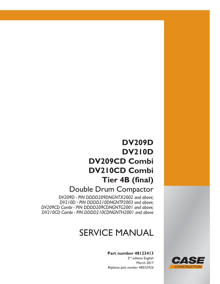
CASE DV210D Combi Tier 4B (final) Double Drum Compactor Service Repair Manual Instant Download
CASE DV210D Combi Tier 4B (final) Double Drum Compactor Service Repair Manual Instant Download
Download Presentation

Please find below an Image/Link to download the presentation.
The content on the website is provided AS IS for your information and personal use only. It may not be sold, licensed, or shared on other websites without obtaining consent from the author. If you encounter any issues during the download, it is possible that the publisher has removed the file from their server.
You are allowed to download the files provided on this website for personal or commercial use, subject to the condition that they are used lawfully. All files are the property of their respective owners.
The content on the website is provided AS IS for your information and personal use only. It may not be sold, licensed, or shared on other websites without obtaining consent from the author.
E N D
Presentation Transcript
DV209D DV210D DV209CD Combi DV210CD Combi Tier 4B (final) Double Drum Compactor DV209D - PIN DDDD209DNGNTX2002 and above; DV210D - PIN DDDD210DNGNTP2003 and above; DV209CD Combi - PIN DDDD209CDNGNTG2001 and above; DV210CD Combi - PIN DDDD210CDNGNTH2001 and above SERVICE MANUAL Part number 48123413 2nd edition English Printed in U.S.A. 2017 CNH Industrial America LLC. All Rights Reserved. Case is a trademark registered in the United States and many other countries, owned or licensed to CNH Industrial N.V., March 2017 Replaces part number 48032926 its subsidiaries or affiliates.
SERVICE MANUAL DV209CD Combi DV209CD Combi Asphalt Compactor - Tier 4B (final) [DDDD209CDNGNTG2001 - ] DV209D TIER 4B (FINAL) Double Drum Compactor [DDDD209DNGNTX2002 - ] DV210CD Combi DV210CD Combi Asphalt Compactor - Tier 4B (final) [DDDD210CDNGNTH2001 - ] DV210D TIER 4B (FINAL) Double Drum Compactor [DDDD210DNGNTP2003 - ] 48123413 29/03/2017 EN
Contents INTRODUCTION Engine....................................................................................... 10 [10.001] Engine and crankcase ............................................................. 10.1 [10.216] Fuel tanks .......................................................................... 10.2 [10.400] Engine cooling system ............................................................. 10.3 [10.500] Selective Catalytic Reduction (SCR) exhaust treatment........................... 10.4 Hydraulic systems....................................................................... 35 [35.000] Hydraulic systems.................................................................. 35.1 [35.300] Reservoir, cooler, and filters........................................................ 35.2 [35.353] Hydraulic travel system ............................................................ 35.3 [35.752] Hydraulic fan drive cooling system................................................. 35.4 [35.995] Compaction/vibration hydraulic system ............................................ 35.5 Frames and ballasting................................................................. 39 [39.100] Frame .............................................................................. 39.1 [39.500] Vibratory roller...................................................................... 39.2 Steering..................................................................................... 41 [41.101] Steering control .................................................................... 41.1 [41.200] Hydraulic control components...................................................... 41.2 [41.206] Pump............................................................................... 41.3 [41.216] Cylinders ........................................................................... 41.4 Wheels...................................................................................... 44 [44.160] Compaction drums ................................................................. 44.1 Cab climate control..................................................................... 50 [50.100] Heating............................................................................. 50.1 Electrical systems....................................................................... 55 [55.015] Engine control system.............................................................. 55.1 48123413 29/03/2017
https://www.ebooklibonline.com Hello dear friend! Thank you very much for reading. Enter the link into your browser. The full manual is available for immediate download. https://www.ebooklibonline.com
[55.050] Heating, Ventilation, and Air-Conditioning (HVAC) control system................. 55.2 [55.100] Harnesses and connectors......................................................... 55.3 [55.301] Alternator........................................................................... 55.4 [55.302] Battery.............................................................................. 55.5 [55.408] Warning indicators, alarms, and instruments ...................................... 55.6 [55.512] Cab controls........................................................................ 55.7 [55.DTC] FAULT CODES.................................................................... 55.8 Platform, cab, bodywork, and decals............................................. 90 [90.151] Cab interior......................................................................... 90.1 [90.150] Cab................................................................................. 90.2 48123413 29/03/2017
INTRODUCTION 48123413 29/03/2017 1
INTRODUCTION Safety rules Double Drum DV NA Personal safety This is the safety alert symbol. It is used to alert you to potential personal injury hazards. Obey all safety messages that follow this symbol to avoid possible death or injury. Throughout this manual you will find the signal words DANGER, WARNING, and CAUTION followed by special in- structions. These precautions are intended for the personal safety of you and those working with you. Read and understand all the safety messages in this manual before you operate or service the machine. DANGER indicates a hazardous situation that, if not avoided, will result in death or serious injury. WARNING indicates a hazardous situation that, if not avoided, could result in death or serious injury. CAUTION indicates a hazardous situation that, if not avoided, could result in minor or moderate injury. FAILURE TO FOLLOW DANGER, WARNING, AND CAUTION MESSAGES COULD RESULT IN DEATH OR SERIOUS INJURY. Machine safety NOTICE: Notice indicates a situation that, if not avoided, could result in machine or property damage. Throughout this manual you will find the signal word Notice followed by special instructions to prevent machine or property damage. The word Notice is used to address practices not related to personal safety. Information NOTE: Note indicates additional information that clarifies steps, procedures, or other information in this manual. Throughout this manual you will find the word Note followed by additional information about a step, procedure, or other information in the manual. The word Note is not intended to address personal safety or property damage. 48123413 29/03/2017 4
INTRODUCTION Personal safety Double Drum DV NA General safety rules Use caution when you operate the machine on slopes. Raised equipment, full tanks and other loads will change the center of gravity of the machine. The machine can tip or roll over when near ditches and embankments or uneven surfaces. Never permit anyone other than the operator to ride on the machine. Never operate the machine under the influence of alcohol or drugs, or while you are otherwise impaired. When digging or using ground-engaging attachments, be aware of buried cables. Contact local utilities to determine the locations of services. Pay attention to overhead power lines and hanging obstacles. High voltage lines may require significant clearance for safety. Hydraulic oil or diesel fuel leaking under pressure can penetrate the skin, causing serious injury or infection. DO NOT use your hand to check for leaks. Use a piece of cardboard or paper. Stop the engine, remove the key, and relieve the pressure before you connect or disconnect fluid lines. Make sure that all components are in good condition. Tighten all connections before you start the engine or pres- surize the system. If hydraulic fluid or diesel fuel penetrates the skin, seek medical attention immediately. Continuous long term contact with hydraulic fluid may cause skin cancer. Avoid long term contact and wash the skin promptly with soap and water. Keep clear of moving parts. Loose clothing, jewelry, watches, long hair, and other loose or hanging items can become entangled in moving parts. Wear protective equipment when appropriate. DO NOT attempt to remove material from any part of the machine while it is being operated or while components are in motion. Make sure that all guards and shields are in good condition and properly installed before you operate the machine. Never operate the machine with shields removed. Always close access doors or panels before you operate the ma- chine. Dirty or slippery steps, ladders, walkways, and platforms can cause falls. Make sure these surfaces remain clean and clear of debris. A person or pet within the operating area of a machine can be struck or crushed by the machine or its equipment. DO NOT allow anyone to enter the work area. Raised equipment and/or loads can fall unexpectedly and crush persons underneath. Never allow anyone to enter the area underneath raised equipment during operation. Never operate the engine in enclosed spaces as harmful exhaust gases may build up. Before you start the machine, be sure that all controls are in neutral or park lock position. Start the engine only from the operator s seat. If you bypass the safety start switch, the engine can start with the transmission in gear. Do not connect or short across terminals on the starter solenoid. Attach jumper cables as described in the manual. Starting in gear may cause death or serious injury. Always keep windows, mirrors, all lighting, and Slow-Moving Vehicle (SMV) emblem clean to provide the best possible visibility while you operate the machine. 48123413 29/03/2017 5
INTRODUCTION Product identification - Machine components Double Drum DV NA 1 RAIL14COM0271HC 48123413 29/03/2017 48
INTRODUCTION 1. 2. 3. 4. 12. 13. 14. 15. Hydraulics tank Fuel tank Sprinkling tank Cab with integrated Roll Over Protective Structure (ROPS) frame Driver s control stand Batteries Combined cooler Air filter Exhaust pipe Sprinkling jets Drum scrapers Front frame Rear frame Front drum Rear drum 5. 6. 7. 8. 9. 10. 11. Engine Hydrostatic pump for travel (roll) Hydrostatic pump for vibration of front drum Hydrostatic pump vibration of rear drum Travel hydrostatic motor Vibration hydrostatic motor Steering joint 16. 17. 18. 19. 20. 21. 22. 48123413 29/03/2017 49
SERVICE MANUAL Engine DV209CD Combi DV209CD Combi Asphalt Compactor - Tier 4B (final) [DDDD209CDNGNTG2001 - ] DV209D TIER 4B (FINAL) Double Drum Compactor [DDDD209DNGNTX2002 - ] DV210CD Combi DV210CD Combi Asphalt Compactor - Tier 4B (final) [DDDD210CDNGNTH2001 - ] DV210D TIER 4B (FINAL) Double Drum Compactor [DDDD210DNGNTP2003 - ] 48123413 29/03/2017 10
Engine - Engine and crankcase Engine - General specification NA NA NA NA DV209CD Combi DV209D DV210CD Combi DV210D Engine type TCD 3.6 L4 Working principle Charging Type of cooling Cylinder arrangement No. of cylinders Bore/stroke Total displacement Combustion process Injection system Exhaust gas recirculation Four-stroke diesel engine Turbocharger with charge air cooling water-cooled in series 4 98 mm (3.86 in) / 120 mm (4.72 in) 3621 cm (221 in ) Direct injection Common Rail externally cooled Oxidation diesel engine catalyst and diesel particulate filter and selective catalytic reduction 2 1-3-4-2 left See engine rating plate See engine rating plate See engine rating plate 4.6 L (1.22 US gal) max. 110 C (230 F) 8 C (15 F) 86 C (187 F) 102 C (216 F) 8 L (2.1 US gal) 125 C (257 F) 80 kPa (11.6 psi) 50 C (122 F) Pre-tensioning: 600 700 N (134.9 157.4 lb) Re-tensioning: 350 450 N (78.7 101.2 lb) Automatic tensioning spring-loaded clamping roller 350 kg (772 lb) Exhaust gas aftertreatment Valves per cylinder Firing order of the engine Direction of rotation looking onto the flywheel Engine power rating according to ISO 3046 Speed (nominal revolutions) Injection timing Coolant volume Permissible continuous coolant temperature Temperature difference between coolant inlet/outlet Start of thermostat opening Thermostat fully open Lubricating oil change volume (with filter) Lube oil temperature in the lube oil tray, maximum Lubricating oil pressure minimum (low idle, engine warm) Permissible maximum combustion air temperature after charge air cooler V-belt tension: V-belts AVX (width: 13 mm) V-rib belt tensioning Weight without cooling system according to DIN 70020-A 48123413 29/03/2017 10.1 [10.001] / 3
Engine - Engine and crankcase Engine - Overview NA NA NA NA DV209CD Combi DV209D DV210CD Combi DV210D 1 RAIL16COM0100FA Exhaust after-treatment system Description S. No 1. 2. 3. 4. 5. 6. 7. 8. 9. 10. 11. 12. 13. Coolant line to pre-heat the AdBlue tank Diesel Exhaust Fluid (DEF) tank Solenoid valve Engine control unit Diesel Exhaust Fluid (DEF) supply pump Selective Catalyst Reduction (SCR) catalytic converter NOX sensor Dosing device Pressure sensor Temperature transmitter Diesel Oxidation Catalytic (DOC) converter Coolant line to cool the dosing device Diesel Exhaust Fluid (DEF) line 48123413 29/03/2017 10.1 [10.001] / 4
Engine - Engine and crankcase Engine - Component identification NA NA NA NA DV209CD Combi DV209D DV210CD Combi DV210D Engine name plate (1) 1 RAIL16COM0003AA View from right 1. Crankcase breather 2. Throttle valve 3. Tension pulley 4. V-rib belt 5. Coolant inlet 6. Lubricating oil drain plug 7. Lube oil replacement filter 8. Lubricating oil dipstick 9. Coolant outlet 10. Differential flow manometer 2 RAIL16COM0079AA View from left 1. Combustion air inlet 2. Lube oil cooler 3. Lubricating oil dipstick (optional) 4. Lube oil replacement filter - Optional 5. Alternator 6. Lubricating oil filling 3 RAIL16COM0080AA 48123413 29/03/2017 10.1 [10.001] / 13
Engine - Engine and crankcase Engine - Remove NA NA NA NA DV209CD Combi DV209D DV210CD Combi DV210D Prior operation: Remove the cab (refer to Cab frame - Remove (90.150)). Prior operation: Remove the platform (refer to Cab floor - Remove (90.150)). Prior operation: Remove the vibration pump for the front drum (refer to Pump - Remove - Front drum vibrations (35.903) ). Prior operation: Remove the vibration pump for the rear drum (refer to Pump - Remove - Rear drum vibrations (35.903) ). Prior operation: Remove the travel pump (refer to Hydraulic travel system - Remove - Travel pump (35.353)). Prior operation: Remove the Diesel Exhaust Fluid (DEF) tank (refer to Diesel Exhaust Fluid (DEF)/AdBlue /ARLA tank - Remove (10.500) 1. Place a suitable drain collector with adequate capacity under the frame to collect the drain oil. NOTE: Approximate drain volume: 9 L (2.4 US gal). 2. Remove the drain plugs and drain the engine oil. 1 RAIL14COM0411AA 3. Remove the tie wraps as required. 2 RAIL14COM0412AA 48123413 29/03/2017 10.1 [10.001] / 14
Engine - Engine and crankcase 4. Unbolt the bracket (2) holding the Engine Control Unit (ECU) (1). 3 RAIL14COM0413AA 5. Unbolt the bracket (3) with the connectors (4). 4 RAIL14COM0414AA 6. Lay the ECU with bracket (1) and connector bracket (3) off to the side. 5 RAIL14COM0415AA 7. Remove the clamps (1) and (2). 8. Remove the ducts (4), (5) and (3) and clamps (1) from the intercooler. 6 RAIL14COM0416AA 48123413 29/03/2017 10.1 [10.001] / 15
Engine - Engine and crankcase 9. Remove the clamp (1). 7 RAIL14COM0417AA 10. Remove the clamp (1) and (2) and then remove the pipe (3). 8 RAIL14COM0418AA 11. Remove the clamp (1). 12. Disconnect the hose (2) to the air cleaner. 9 RAIL14COM0419AA 13. Remove the clamp (1). 14. Remove the duct (2). 10 RAIL16COM0081AA 48123413 29/03/2017 10.1 [10.001] / 16
Engine - Engine and crankcase 15. Close the fuel shut-off valves (1). 11 RAIL14COM0421AA 16. Disconnect the connector (X12) from the fuel pump. 12 RAIL14COM0422AA 17. Disconnect the connector (A) from the fuel pressure sensor. 13 RAIL14COM0423AA 18. DisconnecttheconnectorfromtheWaterinfuelswitch (S38). 14 RAIL14COM0424AA 48123413 29/03/2017 10.1 [10.001] / 17
Engine - Engine and crankcase 19. Remove the hoses (1) and (2) from the filter assem- blies. 15 RAIL14COM0425AA 20. Remove the attaching hardware (1) and bracket (2) with the filter assemblies. 16 RAIL14COM0426AA 21. Disconnect the connector from the coolant level sen- sor. 17 RAIL14COM0427AA 22. Disconnect the hoses (1) and (2). 18 RAIL14COM0428AA 48123413 29/03/2017 10.1 [10.001] / 18
Suggest: If the above button click is invalid. Please download this document first, and then click the above link to download the complete manual. Thank you so much for reading
Engine - Engine and crankcase 23. Remove the clamp (1) and disconnect the hose (2) from the coolant pump. 19 RAIL14COM0429AA 24. Remove the attaching hardware and bracket (1) with the differential lock valve (2). 20 RAIL14COM0430AA 25. Move the bracket assembly out of the work area and secure it with a tie-wrap. 21 RAIL14COM0431AA 26. Disconnect the D+ terminal from the alternator. 22 RAIL14COM0432AA 48123413 29/03/2017 10.1 [10.001] / 19
https://www.ebooklibonline.com Hello dear friend! Thank you very much for reading. Enter the link into your browser. The full manual is available for immediate download. https://www.ebooklibonline.com

