CASE IH AXIAL FLOW 2388 Combine Service Repair Manual Instant Download
CASE IH AXIAL FLOW 2388 Combine Service Repair Manual Instant Download

Download Presentation

Please find below an Image/Link to download the presentation.
The content on the website is provided AS IS for your information and personal use only. It may not be sold, licensed, or shared on other websites without obtaining consent from the author. If you encounter any issues during the download, it is possible that the publisher has removed the file from their server.
You are allowed to download the files provided on this website for personal or commercial use, subject to the condition that they are used lawfully. All files are the property of their respective owners.
The content on the website is provided AS IS for your information and personal use only. It may not be sold, licensed, or shared on other websites without obtaining consent from the author.
E N D
Presentation Transcript
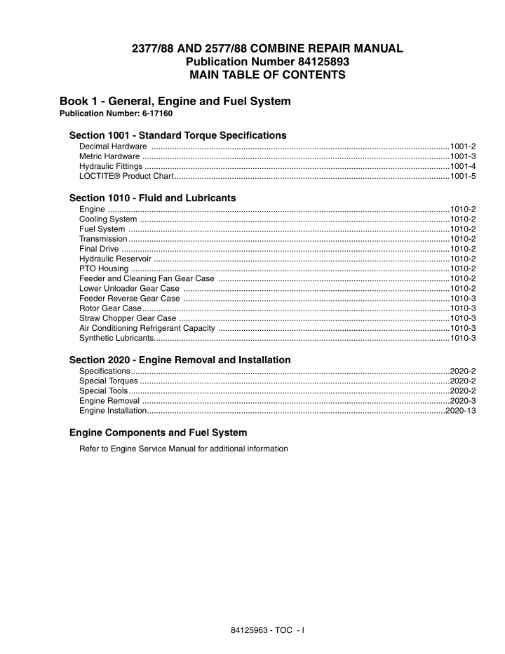
2377/88 AND 2577/88 COMBINE REPAIR MANUAL Publication Number 84125893 MAIN TABLE OF CONTENTS Book 1 - General, Engine and Fuel System Publication Number: 6-17160 Section 1001 - Standard Torque Specifications Decimal Hardware ..................................................................................................................................1001-2 Metric Hardware ......................................................................................................................................1001-3 Hydraulic Fittings .....................................................................................................................................1001-4 LOCTITE Product Chart........................................................................................................................1001-5 Section 1010 - Fluid and Lubricants Engine .....................................................................................................................................................1010-2 Cooling System .......................................................................................................................................1010-2 Fuel System ............................................................................................................................................1010-2 Transmission............................................................................................................................................1010-2 Final Drive ...............................................................................................................................................1010-2 Hydraulic Reservoir .................................................................................................................................1010-2 PTO Housing ...........................................................................................................................................1010-2 Feeder and Cleaning Fan Gear Case .....................................................................................................1010-2 Lower Unloader Gear Case ....................................................................................................................1010-2 Feeder Reverse Gear Case ....................................................................................................................1010-3 Rotor Gear Case......................................................................................................................................1010-3 Straw Chopper Gear Case ......................................................................................................................1010-3 Air Conditioning Refrigerant Capacity .....................................................................................................1010-3 Synthetic Lubricants.................................................................................................................................1010-3 Section 2020 - Engine Removal and Installation Specifications...........................................................................................................................................2020-2 Special Torques .......................................................................................................................................2020-2 Special Tools............................................................................................................................................2020-2 Engine Removal ......................................................................................................................................2020-3 Engine Installation..................................................................................................................................2020-13 Engine Components and Fuel System Refer to Engine Service Manual for additional information 84125963 - TOC - I
Book 2 - Electrical Publication Number: 6-17170 Section 4000 - How It Works Combine Ground Points.............................................................................................................................. 3B-6 Main Valve Assembly Solenoid Functions .................................................................................................. 3B-7 Diode Module Locations ............................................................................................................................. 3B-8 Cranking and Power Distribution Circuit ................................................................................................... 3B-10 Charging Circuit........................................................................................................................................ 3B-11 Power Distribution System........................................................................................................................ 3B-13 Feedback Module ..................................................................................................................................... 3B-14 Fuel Pump................................................................................................................................................. 3B-16 Ether Start................................................................................................................................................. 3B-16 Windshield Wipers.................................................................................................................................... 3B-18 Right Post Instrumentation Center............................................................................................................ 3B-20 Instrumentation "A" Post Changes............................................................................................................ 3B-22 Grain Scan Monitor................................................................................................................................... 3B-24 Shaft Speed Monitor................................................................................................................................. 3B-32 Digital Tachometer.................................................................................................................................... 3B-40 Header Height Display.............................................................................................................................. 3B-43 Calibration................................................................................................................................................. 3B-45 Instrument Panel and Warning Lights....................................................................................................... 3B-57 Warning Lights.......................................................................................................................................... 3B-62 Radio Circuit ............................................................................................................................................. 3B-74 Auxiliary Power Circuit .............................................................................................................................. 3B-75 Air Seat..................................................................................................................................................... 3B-76 Park Brake Circuit..................................................................................................................................... 3B-77 Dead Engine and/or No Hydraulic Pressure Park Brake Release............................................................ 3B-79 Cleaning Fan Speed Circuit...................................................................................................................... 3B-81 Rotor Speed Motor Circuit ........................................................................................................................ 3B-83 Concave Adjustment Circuit...................................................................................................................... 3B-86 Heating Ventilation Air Conditioning System (1999 and earlier)............................................................... 3B-90 Heating Ventilation Air Conditioning System (2000 and later) ................................................................ 3B-102 Lighter, Horn and Dome Lights............................................................................................................... 3B-173 Service Lights, Beacon and Back Lighting.............................................................................................. 3B-183 Power Guide Axle and Variable Propulsion Motor .................................................................................. 3B-184 Header Operation ................................................................................................................................... 3B-185 Reel Operation........................................................................................................................................ 3B-213 Diagnostics - Instrumentation and Header Controller............................................................................. 3B-216 Feeder and Separator Clutch Controls ................................................................................................... 3B-280 Feeder Reverser Controls....................................................................................................................... 3B-283 Header Tilt (Field Tracker ).................................................................................................................... 3B-286 Reel Control Circuit................................................................................................................................. 3B-305 Unloader Control Circuit.......................................................................................................................... 3B-309 84125963 - TOC - II
Book 3 - Electrical and Steering Publication Number: 87571763 Section 4001 - Lighting Circuit Objectives ................................................................................................................................................4001-3 Operators Control ....................................................................................................................................4001-5 Lighting Circuit Components....................................................................................................................4001-7 Service Lights and Sieve Light...............................................................................................................4001-20 Beacon and Back Lighting .....................................................................................................................4001-21 Section 4002 - Wiring Schematics and Troubleshooting, P.I.N. Prior to HAJ0295001 Special Tools............................................................................................................................................4002-3 Fuses and Relay Identification.................................................................................................................4002-4 Instrumentation and Controls...................................................................................................................4002-6 Chassis Connector and Component Locations......................................................................................4002-12 Splice Modules.......................................................................................................................................4002-27 Electrical Connectors.............................................................................................................................4002-33 Electrical Wire Designations..................................................................................................................4002-55 Starter and Power Distribution...............................................................................................................4002-62 Power Distribution System.....................................................................................................................4002-64 Grain Scan Monitor Circuit Testing ........................................................................................................4002-67 Instrumentation......................................................................................................................................4002-72 Rotor Speed Adjustment Motor Circuit ..................................................................................................4002-76 Power Guide Axle and Variable Propulsion............................................................................................4002-81 Header Controller...................................................................................................................................4002-83 Feeder and Separator Controls..............................................................................................................4002-86 Header Tilt .............................................................................................................................................4002-88 Reel and Unloader Control ....................................................................................................................4002-90 Machine Ground Locations....................................................................................................................4002-95 Combine Diagnostics.............................................................................................................................4002-96 Section 4003 - Wiring Schematics and Troubleshooting, P.I.N. HAJ0295001 and After Special Tools............................................................................................................................................4003-3 Fuse Use and Relay Identification ......................................................................................................... 4003-4 Relays .................................................................................................................................................... 4003-5 Machine Ground Locations .................................................................................................................... 4003-6 Instrumentation and Controls ................................................................................................................. 4003-7 Cab Connector and Component Locations ............................................................................................ 4003-9 Chassis Connector and Component Locations .................................................................................... 4003-15 Splice Modules ..................................................................................................................................... 4003-29 Electrical Connectors ........................................................................................................................... 4003-33 Cranking Motor (Starter) and Power Distribution ................................................................................. 4003-52 Power Distribution System.................................................................................................................... 4003-54 Grain Scan Monitor Circuit Testing ...................................................................................................... 4003-57 Instrumentation..................................................................................................................................... 4003-62 Rotor Speed Adjustment Motor Circuit ................................................................................................ 4003-66 Power Guide Axle and Variable Propulsion .......................................................................................... 4003-71 Header Controller ................................................................................................................................. 4003-73 Feeder and Separator Controls ............................................................................................................ 4003-76 Header Tilt ........................................................................................................................................... 4003-78 Reel and Unloader Control .................................................................................................................. 4003-80 Machine Ground Locations .................................................................................................................. 4003-85 Combine Diagnostics ........................................................................................................................... 4003-86 84125963 - TOC - III
https://www.ebooklibonline.com Hello dear friend! Thank you very much for reading. Enter the link into your browser. The full manual is available for immediate download. https://www.ebooklibonline.com
Section 4050 - Neutral Start Switch Neutral Start Switch.................................................................................................................................4050-3 Starting Procedure with Auxiliary Batteries..............................................................................................4050-4 Section 4235 - Battery Servicing and Testing Battery Condition Check..........................................................................................................................4235-2 Specific Gravity Check.............................................................................................................................4235-4 Capacity (Load) Test................................................................................................................................4235-5 Three Minute Charge Test .......................................................................................................................4235-6 Testing Battery Cell with Cadmium Probes..............................................................................................4235-7 Test Procedure for 12-Volt Battery...........................................................................................................4235-8 Battery Leakage Test...............................................................................................................................4235-9 Battery Fast Charging..............................................................................................................................4235-9 Battery Charging....................................................................................................................................4235-10 Activating Dry Charged Batteries...........................................................................................................4235-11 Section 5020 - Steering Hand Pump Special Torques .......................................................................................................................................5020-3 Special Tools............................................................................................................................................5020-2 Pump Removal ........................................................................................................................................5020-3 Pump Disassembly..................................................................................................................................5020-3 Cleaning and Inspection ..........................................................................................................................5020-6 Pump Assembly.......................................................................................................................................5020-8 Pump Installation ...................................................................................................................................5020-12 Section 5030 - Steering Cylinder Special Torques .......................................................................................................................................5030-3 Cylinder Removal.....................................................................................................................................5030-4 Cylinder Installation..................................................................................................................................5030-4 Combines with Power Guide Wheels.......................................................................................................5030-6 Cylinder Disassembly ..............................................................................................................................5030-6 Cylinder Assembly...................................................................................................................................5030-6 Section 5040 - Steering Axle - all except Power Guide Specifications...........................................................................................................................................5040-2 Special Torques .......................................................................................................................................5040-2 Servicing the Wheel Bearing ...................................................................................................................5040-3 Servicing the Tie Rod ..............................................................................................................................5040-5 Toe-In Adjustment....................................................................................................................................5040-7 Spindle Disassembly and Assembly........................................................................................................5040-8 Heavy Duty Spindle Disassembly and Assembly...................................................................................5040-10 Servicing Steering Axle Supports..........................................................................................................5040-12 Axle Pivot Support Installation Positions................................................................................................5040-15 Pivot Support Position Chart..................................................................................................................5040-16 Servicing Axle Pivots .............................................................................................................................5040-18 Axle Extension Mounting Locations.......................................................................................................5040-20 Axle Stabilizer........................................................................................................................................5040-22 Axle Shield.............................................................................................................................................5040-24 Section 5054 - Steering Axle - Power Guide Special Torques .......................................................................................................................................5054-2 Wheel Motor Removal .............................................................................................................................5054-3 Wheel Motor Disassembly.......................................................................................................................5054-4 Wheel Motor Cleaning and Inspection...................................................................................................5054-10 Wheel Motor Assembly..........................................................................................................................5054-12 84125963 - TOC - IV
Cross-Sectional Drawing .......................................................................................................................5054-20 Wheel Motor Installation ........................................................................................................................5054-21 Selector Valve Removal.........................................................................................................................5054-24 Selector Valve Disassembly...................................................................................................................5054-26 Selector Valve Cleaning and Inspection.................................................................................................5054-30 Selector Valve Assembly........................................................................................................................5054-32 Selector Valve Installation......................................................................................................................5054-39 King Pin Removal...................................................................................................................................5054-42 King Pin Cleaning and Inspection..........................................................................................................5054-43 King Pin Installation ...............................................................................................................................5054-44 Toe-In Adjustment..................................................................................................................................5054-47 Propulsion System Air Removal.............................................................................................................5054-48 Section 5080 - Steering Priority Valve Specifications...........................................................................................................................................5080-2 Special Torques .......................................................................................................................................5080-2 Valve Removal .........................................................................................................................................5080-3 Valve Disassembly...................................................................................................................................5080-3 Valve Cleaning and Inspection.................................................................................................................5080-4 Valve Assembly........................................................................................................................................5080-6 Valve Installation......................................................................................................................................5080-8 Removing Air from the System ................................................................................................................5080-9 84125963 - TOC - V
Book 4 - Power Train Publication Number: 84125894 Section 6000 - Hydrostatic Operation Objectives................................................................................................................................................6000-3 System Operations ..................................................................................................................................6000-4 General Information.................................................................................................................................6000-5 System Components................................................................................................................................6000-7 Reservoir and Filtration............................................................................................................................6000-8 System Components and Function..........................................................................................................6000-9 System Operations ................................................................................................................................6000-24 Neutral...............................................................................................................................................6000-25 Charge & Shuttle Pressure Relief......................................................................................................6000-26 Directional Control Valve ...................................................................................................................6000-29 Forward..............................................................................................................................................6000-31 Reverse .............................................................................................................................................6000-35 High Pressure Relief System.................................................................................................................6000-37 Foot-N-Inch Valve..............................................................................................................................6000-40 Internal Pressure Override Control....................................................................................................6000-43 Two Speed Hydrostatic Motor Operation ...............................................................................................6000-44 Test and Adjusting Procedures..............................................................................................................6000-52 Contamination ...................................................................................................................................6000-55 Specifications ....................................................................................................................................6000-56 Purging the System ...........................................................................................................................6000-57 Adjustment of Propulsion Control......................................................................................................6000-58 Pressure Adjustment.........................................................................................................................6000-61 Charge Pressure ...............................................................................................................................6000-62 Servo Pressure..................................................................................................................................6000-66 Two Speed Motor Servo Pressure.....................................................................................................6000-68 Drive Pressure...................................................................................................................................6000-72 Foot-N-Inch Valve..............................................................................................................................6000-74 Internal Pressure Override Valve.......................................................................................................6000-76 Drive Alignment......................................................................................................................................6000-78 Drive Hub...............................................................................................................................................6000-85 Power Guide Axle ..................................................................................................................................6000-86 Electrical System...............................................................................................................................6000-89 System Components & Functions.....................................................................................................6000-90 Valve Ports.........................................................................................................................................6000-92 Wheel Motor Ports.............................................................................................................................6000-93 Valve Low Pressure Shuttle...............................................................................................................6000-94 Disengaged Position..........................................................................................................................6000-98 Intermediate Position.......................................................................................................................6000-100 Engaged Position.............................................................................................................................6000-102 Flow Divider Spools.........................................................................................................................6000-106 Cam Lobe Motor..................................................................................................................................6000-108 How It Works ...................................................................................................................................6000-109 Wheel Motor Flush Circuit...............................................................................................................6000-110 Motor Case Flush System ...............................................................................................................6000-111 Test Procedures...................................................................................................................................6000-113 Start-Up Procedure Rear Wheel Drive............................................................................................6000-114 Specifications ..................................................................................................................................6000-115 Isolating the Problem.......................................................................................................................6000-116 Low Pressure Shuttle Valve.............................................................................................................6000-118 Solenoid Operation..........................................................................................................................6000-120 Selector Spool Operation ................................................................................................................6000-122 Wheel Motor Leakage .....................................................................................................................6000-124 84125963 - TOC - VI
Section 6001 - Hydrostatics Neutral Operation.....................................................................................................................................6001-2 Forward and Reverse...............................................................................................................................6001-3 Swash Plate Position ...............................................................................................................................6001-5 Variable Displacement Pump and Motor..................................................................................................6001-7 Hydrostatic Circuit by Progression...........................................................................................................6001-8 Reservoir................................................................................................................................................6001-11 Heat Exchanger.....................................................................................................................................6001-13 Charge Pump and Check Valve.............................................................................................................6001-15 Inlet Filter...............................................................................................................................................6001-17 Manual Displacement Control Valve......................................................................................................6001-19 High Pressure Relief Valve ....................................................................................................................6001-21 Shuttle and Charge Pressure Relief Valve.............................................................................................6001-23 Foot-N-Inch Valve ..................................................................................................................................6001-25 Internal Pressure Override.....................................................................................................................6001-27 Section 6005 - Hydrostatic Drive System Troubleshooting Transmission Will Not Operate in Either Direction ...................................................................................6005-3 Transmission Operates in One Direction .................................................................................................6005-4 Sluggish Performance..............................................................................................................................6005-4 System Noisy...........................................................................................................................................6005-4 Difficultly in Finding Neutral .....................................................................................................................6005-5 Transmission Operating Hot.....................................................................................................................6005-5 Section 6012 - Hydrostatic Drive System Testing General Test Information..........................................................................................................................6012-2 Special Tools............................................................................................................................................6012-2 Hydrostatic Drive Schematic Symbols.....................................................................................................6012-3 Schematic - Corn/Grain, Single Speed....................................................................................................6012-4 Schematic - Corn/Grain, Two Speed........................................................................................................6012-5 Schematic - Rice, Two Speed..................................................................................................................6012-6 Testing the Hydrostatic Drive System ......................................................................................................6012-7 Section 6015 - Foot-N-Inch Valve Valve Specifications.................................................................................................................................6015-2 Special Tools............................................................................................................................................6015-2 Valve Removal .........................................................................................................................................6015-3 Valve Disassembly...................................................................................................................................6015-3 Valve Inspection.......................................................................................................................................6015-3 Valve Assembly........................................................................................................................................6015-3 Valve Installation......................................................................................................................................6015-4 Foot-N-Inch Pedal Adjustment.................................................................................................................6015-4 Section 6017 - Hydraulic Drive Pump Removal and Installation Drive Pump Specifications ......................................................................................................................6017-2 Pump Special Torques.............................................................................................................................6017-2 Pump Removal and Installation ...............................................................................................................6017-3 Section 6018 - Hydrostatic Drive Pump Pump Special Torques.............................................................................................................................6018-2 Special Tools............................................................................................................................................6018-2 Shop Equipment Tools.............................................................................................................................6018-2 Pump Identification ..................................................................................................................................6018-3 Tools to be Made......................................................................................................................................6018-3 Servicing the Hydrostatic Drive Pump .....................................................................................................6018-4 84125963 - TOC - VII
Charge Pump...........................................................................................................................................6018-8 Power Limiter Valve End Cover................................................................................................................6018-9 Internal Pressure Override Valve...........................................................................................................6018-10 Control Valve..........................................................................................................................................6018-11 Section 6030 - Hydrostatic Drive Motor - Single Speed Special Torques .......................................................................................................................................6030-3 Special Tools............................................................................................................................................6030-3 Motor Identification...................................................................................................................................6030-3 Tools to be Made......................................................................................................................................6030-4 Drive Motor Disassembly.........................................................................................................................6030-4 Drive Motor Assembly..............................................................................................................................6030-4 Relief Valve Block Disassembly and Assembly......................................................................................6030-12 Section 6031 - Hydrostatic Drive Motor - Two Speed Motor Specifications.................................................................................................................................6031-2 Special Torques .......................................................................................................................................6031-3 Special Tools to be Made.........................................................................................................................6031-3 Special Tools............................................................................................................................................6031-4 Hydrostatic Drive Motor - Two Speed ......................................................................................................6031-5 Response Valve Disassembly .............................................................................................................6031-5 Response Valve Assembly ..................................................................................................................6031-5 Block Valve and End Cover Disassembly..........................................................................................6031-16 Block Valve and End Cover Assembly...............................................................................................6031-20 Servo Cylinder Disassembly..............................................................................................................6031-26 Servo Cylinder Assembly ..................................................................................................................6031-28 Barrel Disassembly............................................................................................................................6031-29 Barrel Assembly ................................................................................................................................6031-33 Drive Shaft Seal and Front Cover Disassembly.................................................................................6031-37 Drive Shaft Seal and Front Cover Assembly .....................................................................................6031-40 Swash Plate and Trunnion Service....................................................................................................6031-45 Section 6035 - Transmission and Hydrostatic Drive Motor Hydrostatic Motor Removal and Installation ............................................................................................6035-3 Transmission Removal and Installation....................................................................................................6035-5 Gear Shift Control Cable Adjustment.......................................................................................................6035-8 Propulsion System Air Removal .............................................................................................................6035-9 Section 6040 - Transmission Service Transmission Specifications.....................................................................................................................6040-3 Special Torques .......................................................................................................................................6040-3 Special Tools............................................................................................................................................6040-3 Transmission General Information ...........................................................................................................6040-4 Brake Assembly and Transmission Cover Removal.................................................................................6040-5 Shifter Rails and Shift Fork Removal.......................................................................................................6040-6 Input Housing and Shaft Removal ...........................................................................................................6040-8 Change Gear Shaft Removal and Disassembly.....................................................................................6040-10 Differential Removal and Disassembly ..................................................................................................6040-12 Differential Pinion Shaft Removal and Disassembly..............................................................................6040-15 Differential Pinion Shaft Assembly and Installation................................................................................6040-19 Setting Differential Pinion Shaft End Play..........................................................................................6040-24 Differential Assembly and Installation....................................................................................................6040-26 Measuring Shim Thickness ...............................................................................................................6040-28 Change Gear Shaft Assembly ..............................................................................................................6040-31 Input Housing and Shaft Assembly........................................................................................................6040-33 Change Gear Shaft and Input Housing Installation................................................................................6040-35 84125963 - TOC - VIII
Setting Change Gear Shaft End Play ....................................................................................................6040-37 Measuring Internal Spline Shaft Wear...................................................................................................6040-38 Shifter Rails and Shift Fork Assembly....................................................................................................6040-40 Transission Cover and Brake Installation...............................................................................................6040-43 Cross Sectional Transmission Drawing..................................................................................................6040-45 Section 6060 - Final Drives - Removal and Overhaul Final Drives Specifications.......................................................................................................................6060-2 Special Tools............................................................................................................................................6060-2 Final Drives Removal...............................................................................................................................6060-3 Final Drives Disassembly.........................................................................................................................6060-4 Cleaning and Inspection ..........................................................................................................................6060-8 Final Drives Assembly .............................................................................................................................6060-8 Final Drives Installation..........................................................................................................................6060-15 Section 6061 - Final Drives - Removal and Adjusting Special Torques .......................................................................................................................................6061-2 Final Drives General Information .............................................................................................................6061-2 Final Drives Removal...............................................................................................................................6061-3 Final Drives Installation............................................................................................................................6061-4 Extension and Dual Extension.................................................................................................................6061-4 Final Drives - Small Flange......................................................................................................................6061-6 Final Drives - Large Flange......................................................................................................................6061-8 Section 6064 - PTO - How It Works Objectives ................................................................................................................................................6064-3 PTO Gear Housing...................................................................................................................................6064-4 PTO Housing............................................................................................................................................6064-5 Separator Drive Housing..........................................................................................................................6064-6 Variable Rotor Speed Pulley (Driver).......................................................................................................6064-8 Three Speed Rotor Drive Gearbox ........................................................................................................6064-12 Torque Sensing Pulley (Driven Pulley)...................................................................................................6064-13 Rotor Belt Alignment..............................................................................................................................6064-14 Rotor Drive Alignment Gauge................................................................................................................6064-15 Jackshaft Assembly Alignment ..............................................................................................................6064-16 Variable Rotor Speed Pulley Limit Switches..........................................................................................6064-18 Driven Pulley Adjustment.......................................................................................................................6064-20 Rotor Drive Gearbox..............................................................................................................................6064-21 Section 6065 - PTO Removal and Installation Special Torques .......................................................................................................................................6065-2 Special Tools............................................................................................................................................6065-2 PTO Removal...........................................................................................................................................6065-3 PTO Installation........................................................................................................................................6065-3 Section 6071 - Servicing the PTO Housing Specifications...........................................................................................................................................6071-2 Special Torques .......................................................................................................................................6071-2 Special Tools............................................................................................................................................6071-3 PTO Housing Disassembly......................................................................................................................6071-4 PTO Housing Assembly...........................................................................................................................6071-4 PTO Clutch Disassembly.......................................................................................................................6071-11 PTO Clutch Assembly............................................................................................................................6071-11 84125963 - TOC - IX
Book 5 - Brakes and Hydraulics Publication Number: 84125895 Section 7010 - Brake Assemblies - Removal and Overhaul Specifications...........................................................................................................................................7010-2 Brake Assemblies Disassembly...............................................................................................................7010-3 Brake Assemblies Assembly....................................................................................................................7010-7 Brake Assembly Cross-Section Drawing ...............................................................................................7010-13 Section 7020 - Master Brake Valve Special Torques .......................................................................................................................................7020-2 Specifications...........................................................................................................................................7020-2 Brake Valve Removal...............................................................................................................................7020-3 Brake Valve Disassembly.........................................................................................................................7020-4 Brake Valve Assembly .............................................................................................................................7020-7 Brake Valve Installation..........................................................................................................................7020-12 Section 7030 - European Park Brake Special Torques .......................................................................................................................................7030-2 Specifications...........................................................................................................................................7030-2 Special Tools............................................................................................................................................7030-2 Park Brake Valve Removal.......................................................................................................................7030-3 Park Brake Valve Disassembly ................................................................................................................7030-5 Valve Cleaning and Inspection.................................................................................................................7030-6 Park Brake Valve Assembly.....................................................................................................................7030-6 Park Brake Valve Installation ...................................................................................................................7030-7 Park Brake Cable Adjustment..................................................................................................................7030-9 Charging the Accumulator .....................................................................................................................7030-11 Removing Air from the Brake System....................................................................................................7030-13 Section 8000 - Hydraulics, How It Works Basic Principles of the System ................................................................................................................8000-3 Hydraulic Component Locations..............................................................................................................8000-5 General Information.................................................................................................................................8000-6 Hydraulic Reservoir and Filters................................................................................................................8000-7 Hydraulic Pumps and Drive System ........................................................................................................8000-9 PFC Piston Pump ..................................................................................................................................8000-10 Main Hydraulic Valve Assembly.............................................................................................................8000-19 Signal Circuits........................................................................................................................................8000-20 Steering Priority Valve............................................................................................................................8000-21 Main Valve Assembly.............................................................................................................................8000-27 Reel Raise Valve (SV1) .........................................................................................................................8000-36 Control Valve Operation.........................................................................................................................8000-47 Control Valve Orifice Identification.........................................................................................................8000-48 Unloader Auger Swing Valve .................................................................................................................8000-50 Reel Fore/Aft Valve................................................................................................................................8000-58 Field Tracker Valve ..............................................................................................................................8000-62 Header Valve .........................................................................................................................................8000-68 Accumulator...........................................................................................................................................8000-74 Auxiliary Gear Pump..............................................................................................................................8000-80 Pressure Regulator Valve ......................................................................................................................8000-82 Unloader Auger Clutch Valve.................................................................................................................8000-86 Park Brake Operation.............................................................................................................................8000-94 Tow Valve...............................................................................................................................................8000-98 Feeder Clutch Solenoid .......................................................................................................................8000-100 Reel Drive Valve ..................................................................................................................................8000-102 84125963 - TOC - X
Rotary Air Screen and Separator Drive ...............................................................................................8000-106 Hydraulic System Testing Procedures .................................................................................................8000-109 Test Procedures...................................................................................................................................8000-112 Low Pressure Standby.........................................................................................................................8000-113 High Pressure Standby........................................................................................................................8000-115 Steering Signal Relief Pressure...........................................................................................................8000-117 Reel Drive Relief Pressure...................................................................................................................8000-119 Regulated Pressure.............................................................................................................................8000-121 Field Tracker Park Brake Relief.........................................................................................................8000-123 Auxiliary Gear Pump Flow ...................................................................................................................8000-125 PFC Pump Flow...................................................................................................................................8000-127 Separator and Rotary Air Screen.........................................................................................................8000-129 Section 8001 - Hydraulic Feeder Reverser Drive Feeder Reverser Controls........................................................................................................................8001-3 Feeder Reverser ......................................................................................................................................8001-4 Feeder Reverser Components.................................................................................................................8001-6 Feeder Gearbox Components..................................................................................................................8001-8 Mechanical Components .......................................................................................................................8001-10 Reverser Electrical System....................................................................................................................8001-12 Reverser Hydraulic System....................................................................................................................8001-16 Troubleshooting Procedures ..................................................................................................................8001-18 Section 8005 - Accumulator Specifications...........................................................................................................................................8005-2 Special Torques .......................................................................................................................................8005-2 Special Tools............................................................................................................................................8005-2 Accumulator.............................................................................................................................................8005-3 Charging Accumulator with Nitrogen...................................................................................................8005-3 Illustration of Nitrogen Charging Accumulator Charging Kit ................................................................8005-4 Operational Check and Adjustment .........................................................................................................8005-6 Section 8011 - Hydraulic Schematic and Troubleshooting Hydraulic System Specifications..............................................................................................................8011-3 Special Tools............................................................................................................................................8011-3 Hydraulic Component Locations..............................................................................................................8011-4 Main Valve Assembly Solenoid Locations................................................................................................8011-5 Hydraulic System Troubleshooting...........................................................................................................8011-6 System Weak or Slow..........................................................................................................................8011-6 PFC Piston Pump Remains on High Pressure Standby......................................................................8011-6 PFC Pump - No Flow or Low Flow ......................................................................................................8011-6 PFC Pump Will Not Develop High Pressure Standby..........................................................................8011-6 Header Will Lift and Lower - No Other Main Valve Functions..............................................................8011-7 Reel Will Not Raise - All Other Main Valve Functions Operate ...........................................................8011-7 Reel Will Not Lower - All Other Main Valve Functions Operate...........................................................8011-7 Unloader Will Not Swing - All Other Main Valve Functions Operate....................................................8011-8 Reel Fore/Aft Not Functioning - All Other Main Valve Functions Operate...........................................8011-8 Field Tracker Not Functioning - All Other Main Valve Functions Operate .........................................8011-9 Header Will Not Raise - All Other Main Valve Functions Operate.......................................................8011-9 Header Will Not Lower.........................................................................................................................8011-9 Header Leaks Down, Exceeding 3/4 Inch/Hour at Cylinders.............................................................8011-10 Feeder Reverser Will Not Operate - All Other Main Valve Functions Operate ..................................8011-10 Reel Will Not Turn..............................................................................................................................8011-11 No Regulated Circuit Functions Work................................................................................................8011-11 One Regulated Pressure Function Will Not Operate.........................................................................8011-11 Steering Effort is High........................................................................................................................8011-11 84125963 - TOC - XI
Separator Clutch Will Not Engage.....................................................................................................8011-11 Rotary Air Screen Will Not Rotate.....................................................................................................8011-13 Testing Procedures................................................................................................................................8011-15 Low Pressure Standby Test...............................................................................................................8011-15 High Pressure Standby......................................................................................................................8011-15 Steering Signal Relief Pressure Test.................................................................................................8011-17 Steering Priority Valve.......................................................................................................................8011-18 Reel Drive Standby Pressure Test.....................................................................................................8011-18 Regulated Pressure Test ...................................................................................................................8011-18 Reel Drive Relief Pressure Test.........................................................................................................8011-19 Field Tracker , Park Brake and Feeder Cylinder Thermal Relief Valve Test.....................................8011-20 Brake Test - Manual...........................................................................................................................8011-21 Auxiliary Gear Pump Flow Test..........................................................................................................8011-22 PFC Piston Pump Low Test...............................................................................................................8011-22 Header Valve .........................................................................................................................................8011-24 Header Valve Primary Spools................................................................................................................8011-25 Unloader Swing and Reel Fore/Aft Valves.............................................................................................8011-26 Field Tracker Valve ..............................................................................................................................8011-27 Reel Drive Valve ....................................................................................................................................8011-28 Section 8015 - Pressure Regulator Valve Special Torques .......................................................................................................................................8015-2 Pressure Regulator Valve ........................................................................................................................8015-3 Removing Air from the System ................................................................................................................8015-6 Section 8020 - Auxiliary Gear Pump and PFC Pump PFC Pump Specifications........................................................................................................................8020-2 Auxiliary Gear Pump Specifications.........................................................................................................8020-2 Special Torques - PFC Pump...................................................................................................................8020-3 Special Torques - Auxiliary Gear Pump...................................................................................................8020-3 PFC and Auxiliary Gear Pump Removal..................................................................................................8020-4 Auxiliary Gear Pump Disassembly...........................................................................................................8020-5 PFC Pump Disassembly..........................................................................................................................8020-7 Cleaning and Inspection ........................................................................................................................8020-10 Auxiliary Gear Pump Assembly .............................................................................................................8020-13 PFC Pump Assembly.............................................................................................................................8020-14 PFC and Auxiliary Gear Pump Installation.............................................................................................8020-18 Removing Air from the System ..............................................................................................................8020-19 Section 8030 - Hydraulic Valve Stack Specifications...........................................................................................................................................8030-2 Main Hydraulic Valve Stack .....................................................................................................................8030-3 Removal...............................................................................................................................................8030-3 Main Valve Stack.............................................................................................................................8030-3 Field Tracker and Reel Fore/Aft Valve...........................................................................................8030-4 Header Valve...................................................................................................................................8030-4 Unloading Auger Swing and Reel Raise/Lower Valve.....................................................................8030-4 Disassembly ........................................................................................................................................8030-7 Field Tracker Valve ..........................................................................................................................8030-7 Reel Fore/Aft Valve........................................................................................................................8030-10 Unloader Swing Valve ...................................................................................................................8030-13 Reel Raise/Lower Valve ................................................................................................................8030-16 Header Valve.................................................................................................................................8030-16 Cleaning and Inspection....................................................................................................................8030-19 Assembly...........................................................................................................................................8030-20 Header Valve.................................................................................................................................8030-20 84125963 - TOC - XII
Reel Raise/Lower Valve ................................................................................................................8030-21 Unloader Swing Valve ...................................................................................................................8030-21 Reel Fore/Aft Valve........................................................................................................................8030-22 Field Tracker Valve......................................................................................................................8030-23 Installation .........................................................................................................................................8030-26 Unloader Swing Valve ...................................................................................................................8030-26 Header Valve.................................................................................................................................8030-26 Field Tracker and Reel Fore/Aft Valve ...........................................................................................8030-26 Main Valve Stack...........................................................................................................................8030-26 Removing Air from the System ..............................................................................................................8030-28 Section 8040 - Park Brake and Feeder Clutch Valves Special Torques .......................................................................................................................................8040-2 Specifications...........................................................................................................................................8040-2 Park Brake and Feeder Clutch Valve Removal........................................................................................8040-3 Valve Disassembly...................................................................................................................................8040-4 Cleaning and Inspection ..........................................................................................................................8040-5 Valve Assembly........................................................................................................................................8040-7 Valve Installation......................................................................................................................................8040-9 Valve Adjustment ...................................................................................................................................8040-10 Removing Air from the System ..............................................................................................................8040-10 Section 8050 - Separator Clutch Valves Special Torques .......................................................................................................................................8050-2 Separator Clutch Valve Removal .............................................................................................................8050-3 Unloader Auger Clutch Valve Removal....................................................................................................8050-4 Valve Disassembly...................................................................................................................................8050-5 Cleaning and Inspection ..........................................................................................................................8050-6 Valve Assembly........................................................................................................................................8050-8 Separator Clutch Valve Installation........................................................................................................8050-11 Unloader Auger Clutch Valve Installation...............................................................................................8050-12 Removing Air from the System ..............................................................................................................8050-13 Section 8051 - Separator Drive Test and Troubleshooting General Troubleshooting..........................................................................................................................8051-3 Separator Clutch Control Valve Test........................................................................................................8051-3 Separator Drive Pressure/Flow Testing...................................................................................................8051-4 Separator Pressure Flow Test Diagram...................................................................................................8051-6 Separator Drive Accumulator Test ...........................................................................................................8051-7 Separator Drive Assembly Oil Flush Procedure.......................................................................................8051-7 Section 8055 - Rotary Air Screen and Power-Clean Evacuation System How It Works............................................................................................................................................8055-3 Rotary Air Screen Hydraulic Motor ..........................................................................................................8055-5 Power-Clean Hydraulic Motor ................................................................................................................8055-21 Rotary Air Screen Pump........................................................................................................................8055-25 Section 8060 - Hydraulic Cylinders Special Torques .......................................................................................................................................8060-3 Feeder Clutch Cylinder Removal and Installation....................................................................................8060-4 Separator and Feeder Clutch Disassembly and Assembly......................................................................8060-6 Unloader Tube Swing Cylinder Removal and Installation ........................................................................8060-8 Unloader Tube Swing Cylinder Disassembly and Assembly..................................................................8060-10 Header Lift Cylinder Removal and Installation.......................................................................................8060-12 Header Lift Cylinder Disassembly and Assembly ..................................................................................8060-14 Reel Lift Cylinder Removal and Installation ...........................................................................................8060-16 84125963 - TOC - XIII
Bat Reel Lift Master Cylinder Disassembly and Assembly ....................................................................8060-18 Bat Reel Lift Slave Cylinder Disassembly and Assembly ......................................................................8060-20 Pickup Reel Lift Master Cylinder Disassembly and Assembly...............................................................8060-22 Pickup Reel Lift Slave Cylinder Disassembly and Assembly.................................................................8060-24 Reel Fore/Aft Cylinder Removal and Installation ...................................................................................8060-26 Reel Fore/Aft Cylinder Disassembly and Assembly...............................................................................8060-28 Section 8080 - Reel Drive Control Valve Valve Specifications.................................................................................................................................8080-2 Drive Valve Removal................................................................................................................................8080-3 Drive Valve Disassembly..........................................................................................................................8080-3 Cleaning and Inspection ..........................................................................................................................8080-5 Drive Valve Assembly ..............................................................................................................................8080-7 Drive Valve Installation...........................................................................................................................8080-10 Valve Adjustment ...................................................................................................................................8080-10 Removing Air from the System ..............................................................................................................8080-12 Section 8090 - Reel Drive Motor Motor Specifications.................................................................................................................................8090-2 Reel Drive Motor Removal.......................................................................................................................8090-3 Drive Motor Disassembly.........................................................................................................................8090-3 Cleaning and Inspection ..........................................................................................................................8090-5 Drive Motor Assembly..............................................................................................................................8090-8 Motor Installation....................................................................................................................................8090-10 Removing Air from the System ..............................................................................................................8090-11 84125963 - TOC - XIV
Book 6 - Chassis Publication Number: 87571764 Section 9010 - Air Conditioning Troubleshooting Safety Procedures ...................................................................................................................................9010-4 Special Tools............................................................................................................................................9010-5 Access the Evaporator/Heater Assembly.................................................................................................9010-6 Automatic Temperature Control (ATC).....................................................................................................9010-7 Automatic Temperature Control Systems.................................................................................................9010-9 Temperature Range .................................................................................................................................9010-9 Smart Pressure Switch Cycling System ................................................................................................9010-10 Air Conditioning Operation.....................................................................................................................9010-10 ATC Wiring Schematic...........................................................................................................................9010-12 ATC Troubleshooting..............................................................................................................................9010-13 ATC Electrical Troubleshooting..........................................................................................................9010-13 ATC Fault Codes................................................................................................................................9010-17 High/Low Pressure Switch Circuit Test .............................................................................................9010-20 Blower Potentiometer and Circuit Test...............................................................................................9010-22 Temperature Potentiometer Circuit Test.............................................................................................9010-23 Cab Temperature Sensor Circuit Test................................................................................................9010-24 Evaporator Temp. Sensor Circuit Test ..............................................................................................9010-24 ATC Controller Power Supply and Ground Test.................................................................................9010-25 Blower Motor Power Supply/Ground Test..........................................................................................9010-26 Clutch Relay Power Supply/Ground Test...........................................................................................9010-27 Heater Control Valve Power Supply and Ground Test.......................................................................9010-27 ATC Switch and Circuit Test...............................................................................................................9010-28 PWM Module Power Supply Circuit Test ...........................................................................................9010-28 LCD Display and Circuit Test.............................................................................................................9010-29 Pressurizer Blower Motor Circuit Test................................................................................................9010-29 External Compressor Check..................................................................................................................9010-30 Compressor, Mount Brackets, Fan Belts ...........................................................................................9010-30 Compressor Clutch............................................................................................................................9010-31 Pulley and Belt Alignment..................................................................................................................9010-32 Operational Modes.................................................................................................................................9010-33 Keyed Power - Automatic Mode.........................................................................................................9010-33 Defog/Defrost Mode...........................................................................................................................9010-34 Blower and Temperature Control ...........................................................................................................9010-35 Motor .................................................................................................................................................9010-35 Speed, Temp. Control, LCD Display ...............................................................................................9010-35 Controller Initialization .......................................................................................................................9010-36 Motor .................................................................................................................................................9010-37 ATC Control Switch............................................................................................................................9010-37 ATC Controller........................................................................................................................................9010-38 Low and High Pressure Switches......................................................................................................9010-39 Compressor Clutch............................................................................................................................9010-40 Cab Temperature Check........................................................................................................................9010-41 Air Louvers.........................................................................................................................................9010-41 Air Conditioning Hose Check.............................................................................................................9010-41 Lower Louver Temperature................................................................................................................9010-42 Compressor Hoses............................................................................................................................9010-43 Leak Finding Check...........................................................................................................................9010-43 Heater Hoses.....................................................................................................................................9010-43 Heater Control Valve..........................................................................................................................9010-44 Evaporator and Plenum Check..............................................................................................................9010-45 Cab, Evaporator Temperature Sensors..................................................................................................9010-46 Cab Pressurizer Blower .........................................................................................................................9010-47 ATC Component Locations....................................................................................................................9010-48 84125963 - TOC - XV
Section 9020 - Air Conditioning System Service - System R-134a Specifications...........................................................................................................................................9020-3 Special Torques .......................................................................................................................................9020-3 Special Tools............................................................................................................................................9020-3 Safety Procedures ...................................................................................................................................9020-4 Air Conditioning System Refrigerant Recovery........................................................................................9020-5 Air Conditioning Compressor...................................................................................................................9020-9 Oil Level Check or Adjustment ............................................................................................................9020-9 Injection Method..............................................................................................................................9020-9 Dipstick Method.............................................................................................................................9020-10 Compressor Removal........................................................................................................................9020-12 Compressor Installation.....................................................................................................................9020-13 Compressor Belt Installation and Adjustment....................................................................................9020-15 A/C System Evacuation and Recharging...............................................................................................9020-16 Air Conditioning Compressor Clutch......................................................................................................9020-21 Clutch Removal .................................................................................................................................9020-21 Exploded View Illustration of Clutch ..................................................................................................9020-24 Compressor Clutch Replacement......................................................................................................9020-25 Thermal Expansion Valve Testing..........................................................................................................9020-29 Thermal Expansion Valve Replacement................................................................................................9020-30 ATC Components...................................................................................................................................9020-33 Condenser, Receiver-Drier and Tubes...................................................................................................9020-37 Evaporator Temp. Sensor Installation....................................................................................................9020-38 Blower and Evaporator Illustration .........................................................................................................9020-39 Heater and Evaporator Core..................................................................................................................9020-40 Accessing the Air Conditioning Unit ..................................................................................................9020-40 Core Removal....................................................................................................................................9020-41 Core Installation.................................................................................................................................9020-44 ATC Controller and PWM Module Replacement....................................................................................9020-49 Cab Recirculation Air Filter Service.......................................................................................................9020-50 Cab Intake Air Filter Service..................................................................................................................9020-50 Cab Pressurization Test.........................................................................................................................9020-51 Section 9030 - Air Conditioning System and Compressor Specifications...........................................................................................................................................9030-2 Special Tools............................................................................................................................................9030-2 Safety Procedures ...................................................................................................................................9030-3 A/C System Refrigerant Recovery...........................................................................................................9030-4 Compressor Removal ..............................................................................................................................9030-6 Compressor Installation...........................................................................................................................9030-7 A/C System Evacuation and Recharging.................................................................................................9030-8 Section 9040 - Air Conditioning Components Specifications...........................................................................................................................................9040-3 Special Torques .......................................................................................................................................9040-3 Special Tools............................................................................................................................................9040-3 Safety Procedures ...................................................................................................................................9040-4 Compressor Belt Check and Adjustment.................................................................................................9040-5 Compressor Oil Level Check ...................................................................................................................9040-6 Compressor Clutch Disassembly.............................................................................................................9040-8 Compressor Clutch Assembly................................................................................................................9040-11 Expansion Valve Testing........................................................................................................................9040-15 Evaporator and Expansion Valve...........................................................................................................9040-16 Condenser, Receiver-Drier and Tubes...................................................................................................9040-18 Core Temperature Sensor......................................................................................................................9040-20 Heater and Evaporator Core Removal...................................................................................................9040-22 84125963 - TOC - XVI
Heater and Evaporator Core Installation................................................................................................9040-25 Removing Air from the Cooling System.................................................................................................9040-27 Cab Recirculation Air Filter Service.......................................................................................................9040-28 A/C Control Module Replacing...............................................................................................................9040-28 Operator Cab Intake Air Filter Removal.................................................................................................9040-29 Operator Cab Intake Air Filter Service...................................................................................................9040-29 Section 9100 - Auto Greasing System How the System Works .......................................................................................................................... 9100-3 Manual Start Switch and System Indicator Lamps ................................................................................ 9100-4 Timer Operation ..................................................................................................................................... 9100-5 Filling Reservoir ..................................................................................................................................... 9100-6 50 Hours ................................................................................................................................................ 9100-6 Reservoir Manual Fill ............................................................................................................................. 9100-7 Splicing Broken Lubricating Lines .......................................................................................................... 9100-7 Greasing System ................................................................................................................................... 9100-8 Metering Valve ....................................................................................................................................... 9100-9 Divider Valve ........................................................................................................................................ 9100-10 Check List ............................................................................................................................................ 9100-16 Daily Walk-Around Inspection .............................................................................................................. 9100-16 Troubleshooting .................................................................................................................................... 9100-17 Section 9101 - Separator Drive Jackshaft Specifications...........................................................................................................................................9101-2 Special Torques .......................................................................................................................................9101-2 Jackshaft Service Procedure...................................................................................................................9101-3 Separator Belt Removal...........................................................................................................................9101-3 Jackshaft Removal...................................................................................................................................9101-4 Jackshaft Disassembly.............................................................................................................................9101-5 Jackshaft Assembly ...............................................................................................................................9101-11 Jackshaft Installation..............................................................................................................................9101-21 Separator Belt Installation and Adjustment............................................................................................9101-22 Separator Belt Tightener Pulley Removal..............................................................................................9101-23 Separator Belt Tightener Disassembly ..................................................................................................9101-24 Separator Belt Tightener Assembly .......................................................................................................9101-25 Separator Belt Tightener Installation......................................................................................................9101-27 Section 9102 - Rotor Drive Specifications...........................................................................................................................................9102-2 Special Torques .......................................................................................................................................9102-2 Torque Sensing Unit Removal..................................................................................................................9102-3 Servicing the Torque Sensing Unit...........................................................................................................9102-5 Bushing Replacement..............................................................................................................................9102-9 Illustration of Torque Sensing Unit .........................................................................................................9102-12 Torque Sensing Unit Installation ............................................................................................................9102-13 Section 9103 - Rotor Gearbox General Safety Information......................................................................................................................9103-3 Removal Procedure .................................................................................................................................9103-4 Gearbox Disassembly............................................................................................................................9103-10 Input Shaft Service............................................................................................................................9103-16 Output Shaft Service .........................................................................................................................9103-20 Gearbox Assembly.................................................................................................................................9103-29 Checking End Play and Rolling Torque .............................................................................................9103-36 Gearbox Installation...............................................................................................................................9103-37 84125963 - TOC - XVII
Section 9104 - Rotor Specifications...........................................................................................................................................9104-3 Special Torques .......................................................................................................................................9104-3 Special Tools............................................................................................................................................9104-3 Feeder Housing Removal ........................................................................................................................9104-4 Rotor Removal.........................................................................................................................................9104-9 Rotor Inspection and Repair..................................................................................................................9104-14 Rotor Installation....................................................................................................................................9104-15 Feeder Housing Installation ...................................................................................................................9104-19 Belt Installation and Adjustment.............................................................................................................9104-24 Replacing the Rotor Front Bearing Without Removing the Rotor ..........................................................9104-27 Section 9105 - Rotor Drive Belt Rotor Drive Belt Removal.........................................................................................................................9105-3 Belt Installation.........................................................................................................................................9105-7 Rotor Belt Adjustment..............................................................................................................................9105-9 Rotor Drive Belt and Separator Jackshaft Assembly Alignment ............................................................9105-10 Jackshaft Limit Switch Adjustment.........................................................................................................9105-13 84125963 - TOC - XVIII
Book 7 - Chassis Publication Number: 84125896 Section 9106 - Feeder and Cleaning Fan Gearbox Specifications...........................................................................................................................................9106-2 Special Torques .......................................................................................................................................9106-2 Feeder and Cleaning Fan Gearbox..........................................................................................................9106-3 Section 9107 - Cleaning Fan Drive Fan Drive Specifications ..........................................................................................................................9107-2 Fan Drive Special Torques.......................................................................................................................9107-2 Fan Jackshaft Removal and Disassembly................................................................................................9107-3 Drive Pulley Removal and Disassembly ..................................................................................................9107-7 Fan Speed Control Motor Removal and Disassembly .............................................................................9107-9 Fan Speed Control Motor Assembly and Installation.............................................................................9107-11 Drive Pulley Assembly and Installation..................................................................................................9107-13 Fan Jackshaft Assembly and Installation...............................................................................................9107-14 Section 9109 - Elevator Drive Jackshaft Elevator Drive Jackshaft Specifications ...................................................................................................9109-2 Elevator Drive Jackshaft Special Torques................................................................................................9109-2 Removal of Elevator Drive Jackshaft .......................................................................................................9109-3 Servicing the Elevator Drive Jackshaft.....................................................................................................9109-4 Installation of Elevator Drive Jackshaft ..................................................................................................9109-18 Section 9110 - Inclined Delivery Auger Delivery Auger Special Torques...............................................................................................................9110-2 Delivery Auger Special Tools ...................................................................................................................9110-2 Auger and Sprocket Housing Removal....................................................................................................9110-3 Auger Sprocket Housing Disassembly ....................................................................................................9110-6 Auger Sprocket Housing Assembly..........................................................................................................9110-8 Auger and Sprocket Housing Installation...............................................................................................9110-13 Section 9111 - Discharge Beater Beater Removal .......................................................................................................................................9111-3 Beater Installation....................................................................................................................................9111-7 Section 9113 - Straw Spreader Drive Straw Spreader Drive Specifications........................................................................................................9113-2 Replacing Spreader Drive Belt.................................................................................................................9113-3 Adjusting the Bevel Gear End Play..........................................................................................................9113-9 Spreader Blade Timing and Sensor Gap Check....................................................................................9113-10 Section 9115 - Header Knife Drive Knife Drive Specifications ........................................................................................................................9115-2 Knife Drive Special Torques.....................................................................................................................9115-2 Removal of header Knife Drive Box.........................................................................................................9115-3 Servicing the Knife Drive Box...................................................................................................................9115-5 Installation of Knife Drive Box ................................................................................................................9115-16 84125963 - TOC - XIX
Section 9116 - Tailing Monitor Tailing Monitor Components ....................................................................................................................9116-3 Tailing Monitor Circuit Diagnostics...........................................................................................................9116-4 Section 9117 - Unloader Auger System Unloader Specifications...........................................................................................................................9117-2 Unloader Special Torques........................................................................................................................9117-2 Removal of Lower Unloader Gearbox......................................................................................................9117-3 Servicing the Lower Unloader Gearbox...................................................................................................9117-4 Installation of Lower Unloader Gearbox.................................................................................................9117-11 Removal of Upper Unloader Gearbox....................................................................................................9117-13 Servicing the Upper Unloader Gearbox.................................................................................................9117-14 Installation of Upper Unloader Gearbox.................................................................................................9117-15 Adjusting the Unloader Tube Limit Switches..........................................................................................9117-16 Horizontal Unloading Auger...................................................................................................................9117-17 Grain Tank Auger Cover Adjustment......................................................................................................9117-18 Section 9120 - Field Tracker Tilt Cylinder and Wear Plate Removal and Installation............................................................................9120-2 Tilt Cylinder Disassembly and Assembly.................................................................................................9120-6 Section 9121 - Cross-Flow Fan Cross-Flow Specifications........................................................................................................................9121-3 Fan Special Torques ................................................................................................................................9121-3 Fan Removal............................................................................................................................................9121-4 Fan Installation.........................................................................................................................................9121-5 Section 9125 - Straw Chopper Gearbox Chopper Gearbox specifications..............................................................................................................9125-2 Chopper Gearbox Special Torques..........................................................................................................9125-2 Gearbox Removal....................................................................................................................................9125-3 Servicing Chopper Gearbox Disassembly ...............................................................................................9125-4 Servicing Chopper Gearbox Assembly..................................................................................................9125-11 Gearbox Installation...............................................................................................................................9125-17 Section 9128 - Adjustable Concaves Replacing the Adjustable Concave Control Motor ...................................................................................9128-3 Testing the Position Sensing Potentiometer.............................................................................................9128-7 84125963 - TOC - XX
1001 Section 1001 STANDARD TORQUE SPECIFICATIONS AND LOCTITE CHART 2004 CNH America LLC Printed in U.S.A. Issued October, 2004
1001-2 TABLE OF CONTENTS TORQUE SPECIFICATIONS - DECIMAL HARDWARE ...................................................................................... 2 TORQUE SPECIFICATIONS - METRIC HARDWARE ........................................................................................ 3 TORQUE SPECIFICATIONS - STEEL HYDRAULIC FITTINGS ......................................................................... 4 TORQUE SPECIFICATIONS - STEEL HYDRAULIC FITTINGS ......................................................................... 5 TORQUE SPECIFICATIONS - DECIMAL HARDWARE Use the torques in this chart when special torques are not given. These torques apply to fasteners with both UNC and UNF threads as received from suppliers dry, or when lubricated with engine oil. Not applicable if special graphities, Molydisulfide greases, or other extreme pressure lubricants are used. Grade 8 Bolts, Nuts, and Studs Pound- Inches 144 to 180 288 to 348 540 to 648 Pound- Feet 70 to 84 110 to 132 160 to 192 220 to 264 380 to 456 600 to 720 900 to 1080 1280 to 1440 1820 to 2000 2380 to 2720 3160 to 3560 Newton metres 16 to 20 33 to 39 61 to 73 Newton metres 95 to 114 149 to 179 217 to 260 298 to 358 515 to 618 814 to 976 1220 to 1465 1736 to 1953 2468 to 2712 3227 to 3688 4285 to 4827 Size 1/4 inch 5/16 inch 3/8 inch Grade 5 Bolts, Nuts, and Studs Size 7/16 inch 1/2 inch 9/16 inch 5/8 inch 3/4 inch 7/8 inch 1.0 inch 1-1/8 inch 1-1/4 inch 1-3/8 inch 1-1/2 inch NOTE: Use thick nuts with Grade 8 bolts. Pound- Inches 108 to 132 204 to 252 420 to 504 Pound- Feet 54 to 64 80 to 96 110 to 132 150 to 180 270 to 324 400 to 480 580 to 696 800 to 880 1120 to 1240 1460 to 1680 1940 to 2200 Newton metres 12 to 15 23 to 28 48 to 57 Newton metres 73 to 87 109 to 130 149 to 179 203 to 244 366 to 439 542 to 651 787 to 944 1085 to 1193 1519 to 1681 1980 to 2278 2631 to 2983 Size 1/4 inch 5/16 inch 3/8 inch Size 7/16 inch 1/2 inch 9/16 inch 5/8 inch 3/4 inch 7/8 inch 1.0 inch 1-1/8 inch 1-1/4 inch 1-3/8 inch 1-1/2 inch Issued 10-04
1001-3 TORQUE SPECIFICATIONS - METRIC HARDWARE Use the following torques when specifications are not given. Grade 10.9 Bolts, Nuts, and Studs These values apply to fasteners with coarse threads as received from supplier, plated or unplated, or when lubricated with engine oil. These values do not apply if graphite or Molydisulfide grease or oil is used. 10.9 Pound- Inches 36 to 48 84 to 96 132 to 156 324 to 384 Pound- Feet 54 to 64 93 to 112 149 to 179 230 to 280 450 to 540 780 to 940 1470 to 1770 2580 to 3090 Newton metres 4 to 5 9 to 11 15 to 18 37 to 43 Newton metres 73 to 87 125 to 150 200 to 245 310 to 380 610 to 730 1050 to 1275 2000 to 2400 3500 to 4200 Size M4 M5 M6 M8 Grade 8.8 Bolts, Nuts, and Studs 8.8 Size M10 M12 M14 M16 M20 M24 M30 M36 Pound- Inches 24 to 36 60 to 72 96 to 108 228 to 276 456 to 540 Pound- Feet 66 to 79 106 to 127 160 to 200 320 to 380 500 to 600 920 to 1100 1600 to 1950 Newton metres 3 to 4 7 to 8 11 to 12 26 to 31 52 to 61 Newton metres 90 to 107 144 to 172 217 to 271 434 to 515 675 to 815 1250 to 1500 2175 to 2600 Size M4 M5 M6 M8 M10 Size M12 M14 M16 M20 M24 M30 M36 Grade 12.9 Bolts, Nuts, and Studs 12.9 Usually the torque values specified for grade 10.9 fasteners can be used satisfactorily on grade 12.9 fasteners. Issued 10-04
Suggest: If the above button click is invalid. Please download this document first, and then click the above link to download the complete manual. Thank you so much for reading
Template Name: SM_2_col Template Date: 1994_04_05 Alt= to hide template information Alt+ to display template information 2020-3 ENGINE REMOVAL STEP 1 STEP 4 1 RP96H237 RP96H230 Disconnect the battery ground cable (1) and ground wires from the negative terminal of each battery. Park the combine on a hard, level surface and turn the engine off. Put blocks in front of and behind the drive wheels. STEP 5 STEP 2 1 RP96H238 RP96H231 At the right side of the combine, remove the rear screen. Open the radiator drain valve (1) and drain the coolant. Close and securely tighten the drain valve after the coolant has drained from the radiator. At the left side of the combine, raise the front and rear panels and open the front screen to gain access to the batteries. STEP 3 STEP 6 1 2 3 RP96H236 RP96H240 Remove the two clips and remove the battery box cover. Loosen the hose clamp (1) and disconnect the hose from the precleaner. Loosen the clamp (2) on the precleaner (3) and remove the precleaner. Issued 10-04 Printed in U.S.A.
https://www.ebooklibonline.com Hello dear friend! Thank you very much for reading. Enter the link into your browser. The full manual is available for immediate download. https://www.ebooklibonline.com