CASE IH AXIAL-FLOW 9240 Tier 4B (final) Combine Service Repair Manual Instant Download
CASE IH AXIAL-FLOW 9240 Tier 4B (final) Combine Service Repair Manual Instant Download

Download Presentation

Please find below an Image/Link to download the presentation.
The content on the website is provided AS IS for your information and personal use only. It may not be sold, licensed, or shared on other websites without obtaining consent from the author. If you encounter any issues during the download, it is possible that the publisher has removed the file from their server.
You are allowed to download the files provided on this website for personal or commercial use, subject to the condition that they are used lawfully. All files are the property of their respective owners.
The content on the website is provided AS IS for your information and personal use only. It may not be sold, licensed, or shared on other websites without obtaining consent from the author.
E N D
Presentation Transcript
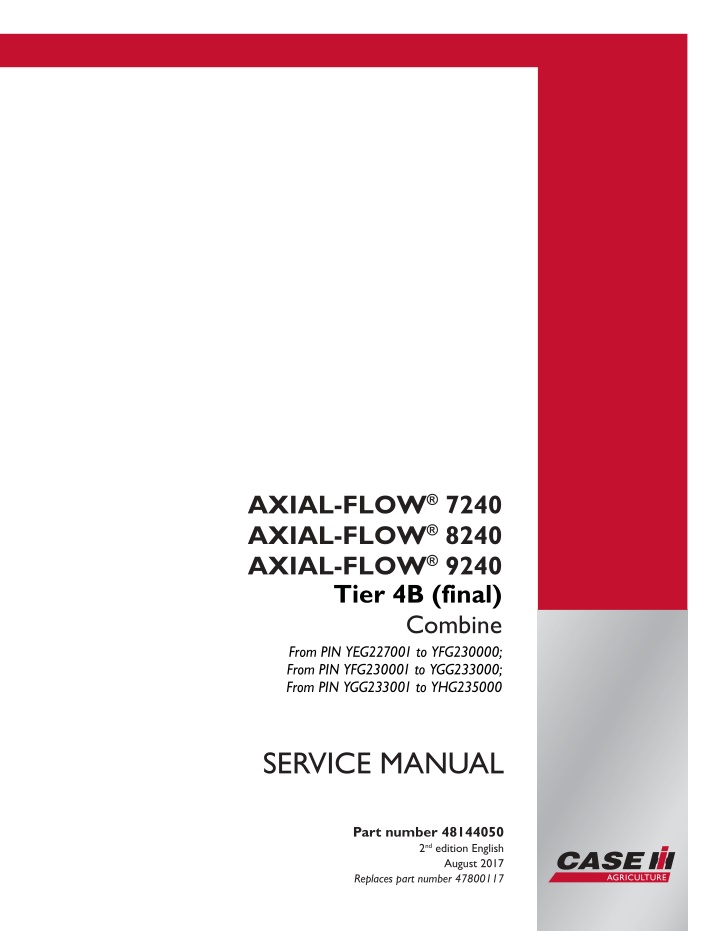
AXIAL-FLOW 7240 AXIAL-FLOW 8240 AXIAL-FLOW 9240 Tier 4B (final) Combine From PIN YEG227001 to YFG230000; From PIN YFG230001 to YGG233000; From PIN YGG233001 to YHG235000 SERVICE MANUAL Part number 48144050 2nd edition English Printed in U.S.A. 2017 CNH Industrial America LLC. All Rights Reserved. Case IH is a trademark registered in the United States and many other countries, owned or licensed to CNH Industrial N.V., August 2017 Replaces part number 47800117 its subsidiaries or affiliates.
Link Product / Engine Product Market Product North America Engine AXIAL-FLOW 7240 Tier 4b (final) [YEG227001 - YFG230000] AXIAL-FLOW 7240 Tier 4b (final) [YFG230001 - YGG233000] AXIAL-FLOW 7240 Tier 4b (final) [YGG233001 - YHG235000] AXIAL-FLOW 8240 Tier 4b (final) [YEG227001 - YFG230000] AXIAL-FLOW 8240 Tier 4b (final) [YFG230001 - YGG233000] AXIAL-FLOW 8240 Tier 4b (final) [YGG233001 - YHG235000] AXIAL-FLOW 9240 Tier 4b (final) [YEG227001 - YFG230000] AXIAL-FLOW 9240 Tier 4b (final) [YFG230001 - YGG233000] AXIAL-FLOW 9240 Tier 4b (final) [YGG233001 - YHG235000] F3GFE613A*B001 North America F3GFE613A*B001 North America F3GFE613A*B001 North America F3HFE613A*B003 North America F3HFE613A*B003 North America F3HFE613A*B003 North America F3JFE613A*B001 North America F3JFE613A*B001 North America F3JFE613A*B001 48144050 25/08/2017
Contents INTRODUCTION Engine....................................................................................... 10 [10.001] Engine and crankcase ............................................................. 10.1 [10.202] Air cleaners and lines .............................................................. 10.2 [10.210] Lift pump and lines ................................................................. 10.3 [10.216] Fuel tanks .......................................................................... 10.4 [10.254] Intake and exhaust manifolds and muffler ......................................... 10.5 [10.304] Engine lubrication system.......................................................... 10.6 [10.310] Aftercooler.......................................................................... 10.7 [10.400] Engine cooling system ............................................................. 10.8 [10.414] Fan and drive ...................................................................... 10.9 [10.419] Stationary air screen ............................................................. 10.10 [10.450] Engine air compressor ........................................................... 10.11 [10.500] Selective Catalytic Reduction (SCR) exhaust treatment......................... 10.12 Main gearbox and drive............................................................... 14 [14.100] Main gearbox and drive ............................................................ 14.1 Transmission.............................................................................. 21 [21.100] Mechanical transmission hydraulic components................................... 21.1 [21.114] Mechanical transmission ........................................................... 21.2 [21.130] Mechanical transmission external controls......................................... 21.3 [21.145] Gearbox internal components...................................................... 21.4 [21.182] Differential.......................................................................... 21.5 Front axle system ....................................................................... 25 [25.100] Powered front axle ................................................................. 25.1 [25.108] Final drive hub, steering knuckles, and shafts ..................................... 25.2 [25.310] Final drives......................................................................... 25.3 48144050 25/08/2017
https://www.ebooklibonline.com Hello dear friend! Thank you very much for reading. Enter the link into your browser. The full manual is available for immediate download. https://www.ebooklibonline.com
Rear axle system........................................................................ 27 [27.100] Powered rear axle.................................................................. 27.1 [27.550] Non-powered rear axle............................................................. 27.2 Hydrostatic drive......................................................................... 29 [29.100] Transmission and steering hydrostatic control..................................... 29.1 [29.134] Two-speed assembly............................................................... 29.2 [29.202] Hydrostatic transmission ........................................................... 29.3 [29.218] Pump and motor components...................................................... 29.4 [29.300] Rear hydrostatic transmission...................................................... 29.5 Power Take-Off (PTO)................................................................. 31 [31.146] Front Power Take-Off (PTO) ....................................................... 31.1 Brakes and controls .................................................................... 33 [33.110] Parking brake or parking lock ...................................................... 33.1 [33.202] Hydraulic service brakes ........................................................... 33.2 Hydraulic systems....................................................................... 35 [35.000] Hydraulic systems.................................................................. 35.1 [35.102] Pump control valves................................................................ 35.2 [35.106] Variable displacement pump ....................................................... 35.3 [35.220] Auxiliary hydraulic pump ........................................................... 35.4 [35.300] Reservoir, cooler, and filters........................................................ 35.5 [35.350] Safety and main relief valves ...................................................... 35.6 [35.359] Main control valve.................................................................. 35.7 [35.410] Header or attachment height system .............................................. 35.8 [35.440] Grain tank unload system.......................................................... 35.9 [35.518] Reel control system .............................................................. 35.10 [35.536] Crop processor system .......................................................... 35.11 [35.752] Hydraulic fan drive cooling system............................................... 35.12 [35.796] Chaff spreader control ........................................................... 35.13 48144050 25/08/2017
Steering..................................................................................... 41 [41.101] Steering control .................................................................... 41.1 [41.106] Tie rods............................................................................. 41.2 [41.200] Hydraulic control components...................................................... 41.3 [41.216] Cylinders ........................................................................... 41.4 [41.432] Autoguidance steering ............................................................. 41.5 Wheels...................................................................................... 44 [44.511] Front wheels........................................................................ 44.1 Tracks and track suspension........................................................ 48 [48.100] Tracks .............................................................................. 48.1 [48.130] Track frame and driving wheels.................................................... 48.2 [48.134] Track tension units ................................................................. 48.3 [48.138] Track rollers ........................................................................ 48.4 Cab climate control..................................................................... 50 [50.100] Heating............................................................................. 50.1 [50.104] Ventilation .......................................................................... 50.2 [50.200] Air conditioning..................................................................... 50.3 Electrical systems....................................................................... 55 [55.000] Electrical system ................................................................... 55.1 [55.010] Fuel injection system............................................................... 55.2 [55.011] Fuel tank system ................................................................... 55.3 [55.012] Engine cooling system ............................................................. 55.4 [55.013] Engine oil system .................................................................. 55.5 [55.014] Engine intake and exhaust system................................................. 55.6 [55.015] Engine control system.............................................................. 55.7 [55.019] Hydrostatic drive control system ................................................... 55.8 [55.020] Transmission speed sensors....................................................... 55.9 [55.023] Transmission position sensors and switches .................................... 55.10 48144050 25/08/2017
[55.024] Transmission control system..................................................... 55.11 [55.030] Service brake electrical system .................................................. 55.12 [55.031] Parking brake electrical system.................................................. 55.13 [55.036] Hydraulic system control ......................................................... 55.14 [55.046] Rear axle control system......................................................... 55.15 [55.047] Steering control system .......................................................... 55.16 [55.050] Heating, Ventilation, and Air-Conditioning (HVAC) control system............... 55.17 [55.100] Harnesses and connectors....................................................... 55.18 [55.201] Engine starting system........................................................... 55.19 [55.202] Cold start aid ..................................................................... 55.20 [55.301] Alternator......................................................................... 55.21 [55.302] Battery............................................................................ 55.22 [55.404] External lighting .................................................................. 55.23 [55.405] External lighting switches and relays ............................................ 55.24 [55.408] Warning indicators, alarms, and instruments .................................... 55.25 [55.421] Feeding control system .......................................................... 55.26 [55.422] Ejection/Unloading control system ............................................... 55.27 [55.423] Cleaning control system.......................................................... 55.28 [55.426] Harvest material flow control system............................................. 55.29 [55.512] Cab controls...................................................................... 55.30 [55.514] Cab lighting ...................................................................... 55.31 [55.518] Wiper and washer system........................................................ 55.32 [55.520] Cab harvesting controls.......................................................... 55.33 [55.525] Cab engine controls.............................................................. 55.34 [55.624] Residue handling control......................................................... 55.35 [55.628] Threshing electrical control ...................................................... 55.36 [55.640] Electronic modules............................................................... 55.37 [55.662] Header height control ............................................................ 55.38 48144050 25/08/2017
[55.670] Header leveling control........................................................... 55.39 [55.675] Reel speed and position control.................................................. 55.40 [55.680] Autopilot/Autoguidance .......................................................... 55.41 [55.780] Shaker shoe leveling system control............................................. 55.42 [55.834] Sieve electric control ............................................................. 55.43 [55.836] Rotary separator control ......................................................... 55.44 [55.988] Selective Catalytic Reduction (SCR) electrical system .......................... 55.45 [55.DTC] FAULT CODES.................................................................. 55.46 Product feeding.......................................................................... 60 [60.105] Floating roll, feed chain, and drive ................................................. 60.1 [60.110] Feeder housing..................................................................... 60.2 [60.112] Stone trapping system ............................................................. 60.3 [60.120] Header drive system ............................................................... 60.4 [60.150] Feeder drive system ............................................................... 60.5 Threshing .................................................................................. 66 [66.000] Threshing .......................................................................... 66.1 [66.101] Concave conveyor plate ........................................................... 66.2 [66.110] Concave control system............................................................ 66.3 [66.260] Threshing mechanism drive system ............................................... 66.4 [66.331] Rotor ............................................................................... 66.5 Separation................................................................................. 72 [72.430] Separator grates ................................................................... 72.1 Residue handling........................................................................ 73 [73.210] Straw chopper drive system........................................................ 73.1 [73.215] Straw chopper electro-magnetic clutch support.................................... 73.2 [73.230] Straw chopper...................................................................... 73.3 [73.430] Straw spreader..................................................................... 73.4 Cleaning.................................................................................... 74 48144050 25/08/2017
[74.000] Cleaning............................................................................ 74.1 [74.100] Self-leveling frame ................................................................. 74.2 [74.101] Cleaning drive systems ............................................................ 74.3 [74.110] Grain pan........................................................................... 74.4 [74.114] Upper shaker shoe ................................................................. 74.5 [74.118] Lower shaker shoe ................................................................. 74.6 [74.130] Fan housing........................................................................ 74.7 [74.136] Fan drive system................................................................... 74.8 [74.140] Tailings return system.............................................................. 74.9 Crop storage / Unloading............................................................. 80 [80.101] Clean grain elevator................................................................ 80.1 [80.150] Grain tank .......................................................................... 80.2 [80.175] Grain tank unload drive system .................................................... 80.3 [80.180] Grain tank unload .................................................................. 80.4 Platform, cab, bodywork, and decals............................................. 90 [90.100] Engine hood and panels ........................................................... 90.1 [90.105] Machine shields and guards ....................................................... 90.2 [90.118] Protections and footboards......................................................... 90.3 [90.124] Pneumatically-adjusted operator seat.............................................. 90.4 [90.150] Cab................................................................................. 90.5 [90.151] Cab interior......................................................................... 90.6 48144050 25/08/2017
INTRODUCTION 48144050 25/08/2017 1
INTRODUCTION Safety rules Personal safety This is the safety alert symbol. It is used to alert you to potential personal injury hazards. Obey all safety messages that follow this symbol to avoid possible death or injury. Throughout this manual you will find the signal words DANGER, WARNING, and CAUTION followed by special in- structions. These precautions are intended for the personal safety of you and those working with you. Read and understand all the safety messages in this manual before you operate or service the machine. DANGER indicates a hazardous situation that, if not avoided, will result in death or serious injury. WARNING indicates a hazardous situation that, if not avoided, could result in death or serious injury. CAUTION indicates a hazardous situation that, if not avoided, could result in minor or moderate injury. FAILURE TO FOLLOW DANGER, WARNING, AND CAUTION MESSAGES COULD RESULT IN DEATH OR SERIOUS INJURY. Machine safety NOTICE: Notice indicates a situation that, if not avoided, could result in machine or property damage. Throughout this manual you will find the signal word Notice followed by special instructions to prevent machine or property damage. The word Notice is used to address practices not related to personal safety. Information NOTE: Note indicates additional information that clarifies steps, procedures, or other information in this manual. Throughout this manual you will find the word Note followed by additional information about a step, procedure, or other information in the manual. The word Note is not intended to address personal safety or property damage. 48144050 25/08/2017 5
INTRODUCTION Safety rules - Ecology and the environment Soil, air, and water quality is important for all industries and life in general. When legislation does not yet rule the treatment of some of the substances that advanced technology requires, sound judgment should govern the use and disposal of products of a chemical and petrochemical nature. Familiarize yourself with the relative legislation applicable to your country, and make sure that you understand this legislation. Where no legislation exists, obtain information from suppliers of oils, filters, batteries, fuels, anti-freeze, cleaning agents, etc., with regard to the effect of these substances on man and nature and how to safely store, use, and dispose of these substances. Helpful hints Avoid the use of cans or other inappropriate pressurized fuel delivery systems to fill tanks. Such delivery systems may cause considerable spillage. In general, avoid skin contact with all fuels, oils, acids, solvents, etc. Most of these products contain substances that may be harmful to your health. Modern oils contain additives. Do not burn contaminated fuels and or waste oils in ordinary heating systems. Avoid spillage when you drain fluids such as used engine coolant mixtures, engine oil, hydraulic fluid, brake fluid, etc. Do not mix drained brake fluids or fuels with lubricants. Store all drained fluids safely until you can dispose of the fluids in a proper way that complies with all local legislation and available resources. Do not allow coolant mixtures to get into the soil. Collect and dispose of coolant mixtures properly. The air-conditioning system contains gases that should not be released into the atmosphere. Consult an air-condi- tioning specialist or use a special extractor to recharge the system properly. Repair any leaks or defects in the engine cooling system or hydraulic system immediately. Do not increase the pressure in a pressurized circuit as this may lead to a component failure. Protect hoses during welding. Penetrating weld splatter may burn a hole or weaken hoses, allowing the loss of oils, coolant, etc. Battery recycling Batteries and electric accumulators contain several substances that can have a harmful effect on the environment if the batteries are not properly recycled after use. Improper disposal of batteries can contaminate the soil, groundwater, and waterways. CASE IH strongly recommends that you return all used batteries to a CASE IH dealer, who will dispose of the used batteries or recycle the used batteries properly. In some countries, this is a legal requirement. Mandatory battery recycling NOTE: The following requirements are mandatory in Brazil. Batteries are made of lead plates and a sulfuric acid solution. Because batteries contain heavy metals such as lead, CONAMA Resolution 401/2008 requires you to return all used batteries to the battery dealer when you replace any batteries. Do not dispose of batteries in your household garbage. Points of sale are obliged to: Accept the return of your used batteries Store the returned batteries in a suitable location Send the returned batteries to the battery manufacturer for recycling 48144050 25/08/2017 6
INTRODUCTION Safety rules Repair and maintenance All repair and maintenance works listed in this manual must be carried out only by qualified dealership personnel, strictly complying with the instructions given; and using, whenever possible, the special tools. Anyone who carries out the above operations without complying with the procedures shall be responsible for the subsequent damages. The manufacturer and all the organizations of it's distribution chain, including - without limitation - national, regional, or local dealers, reject any responsibility for damages due to the anomalous behavior of parts and/or components not approved by the manufacturer himself, including those used for the servicing or repair of the product manufactured or marketed by the manufacturer. In any case, no warranty is given or attributed on the product manufactured or marketed by the manufacturer in case of damages due to an anomalous behavior of parts and/or components not approved by the manufacturer. The information in this manual is up-to-date at the date of the publication. It is the policy of the manufacturer for continuous improvement. Some information could not be updated due to modifications of a technical or commercial type, as well as to suit the laws and regulations of different countries. In case of questions, refer to your Sales and Service Networks. 48144050 25/08/2017 7
INTRODUCTION 2 NHPH12AF03459AA 3 NHPE12AF02836AA 48144050 25/08/2017 22
SERVICE MANUAL Engine AXIAL-FLOW 7240 Tier 4b (final) [YEG227001 - YFG230000], AXIAL-FLOW 7240 Tier 4b (final) [YFG230001 - YGG233000], AXIAL-FLOW 7240 Tier 4b (final) [YGG233001 - YHG235000], AXIAL-FLOW 8240 Tier 4b (final) [YEG227001 - YFG230000], AXIAL-FLOW 8240 Tier 4b (final) [YFG230001 - YGG233000], AXIAL-FLOW 8240 Tier 4b (final) [YGG233001 - YHG235000], AXIAL-FLOW 9240 Tier 4b (final) [YEG227001 - YFG230000], AXIAL-FLOW 9240 Tier 4b (final) [YFG230001 - YGG233000], AXIAL-FLOW 9240 Tier 4b (final) [YGG233001 - YHG235000] 48144050 25/08/2017 10
Engine - Engine and crankcase Engine - Remove - Cursor 11 and 13 NA NA AXIAL-FLOW 7240 AXIAL-FLOW 8240 WARNING Avoid injury! Always do the following before lubricating, maintaining, or servicing the machine. 1. Disengage all drives. 2. Engage parking brake. 3. Lower all attachments to the ground, or raise and engage all safety locks. 4. Shut off engine. 5. Remove key from key switch. 6. Switch off battery key, if installed. 7. Wait for all machine movement to stop. Failure to comply could result in death or serious injury. W0047A WARNING Heavy objects! Lift and handle all heavy components using lifting equipment with adequate capacity. Always support units or parts with suitable slings or hooks. Make sure the work area is clear of all bystanders. Failure to comply could result in death or serious injury. W0398A Prior operation: Remove the oil drain hose. See Engine - Remove engine oil drain line and drain valve (10.001) Prior operation: Radiator - Drain fluid (10.400) Prior operation: Deaeration tank - Remove (10.400) Prior operation: Engine hood and panels - Remove (90.100) Prior operation: Radiator hoses - Remove (10.400) Prior operation: Central wiring harness - Remove (55.100) Prior operation: Aftercooler air supply and return lines - Remove air supply tube (10.310) Prior operation: Aftercooler air supply and return lines - Remove air return tube (10.310) Prior operation: Air cleaner connection between filter and engine - Remove (10.202) Prior operation: Connection tube from filter to muffler - Remove (10.202) Prior operation: Fan and drive - Remove (10.414) Prior operation: Air-conditioning compressor - Remove (50.200) Prior operation: Fuel supply lines Low pressure - Remove from the engine (10.210) Prior operation: Fuel return lines - Remove from the engine (10.210) Prior operation: Exhaust muffler - Remove mixer tube (10.254) Prior operation: Exhaust muffler - Remove exhaust tube from turbo charger to Diesel Oxidation Catalyst (DOC) (10.254) Prior operation: Diesel Exhaust Fluid (DEF)/AdBlue /ARLA lines - Remove DEF hose bundle from the engine compartment (10.500) Prior operation: Selective Catalytic Reduction (SCR) muffler and catalyst - Remove (10.500) Prior operation: 48144050 25/08/2017 10.1 [10.001] / 3
Engine - Engine and crankcase Diesel Oxidation Catalyst (DOC) - Remove (10.500) NOTE: Illustrations are for reference only. It may not be the actual engine. 1. Disengage the battery connect switch (1). 1 NHIL13AF00586AA 2. Attach a suitable lift chain to the front lift eye (1) at the front of the engine. 2 NHIL14AF00431AA 3. Attach a suitable lift chain to the back lift eye (1) at the rear of the engine. 3 NHIL14AF00432AA 48144050 25/08/2017 10.1 [10.001] / 4
Engine - Engine and crankcase 4. Connect the lift chain to a suitable lifting device. 5. Raise the lifting device enough to support the engine during removal of the engine mounting bolts. NOTE: The lifting device should be rated for at least 907.2 kg (2000 lb). Allow enough clearance to lift the engine from the combine, approximately 7.0 m (23 ft) from the floor. 4 10013136 6. From the grain tank side of the engine, loosen the front, enginemountingbolts(1). Donotremovethemounting bolts at this time. 7. From the platform side, loosen the front, engine mount- ing bolts (2). Do not remove the mounting bolts at this time. 5 NHIL14AF01001AA 8. From the rear of the engine, loosen but do not remove all the bolts and washers (1) that couple the engine to the gearbox. There are twelve bolts and washers in total. 9. For safety reasons to the radiators, place a sheet of plywood, cut to size, in front of the cooler box for pro- tection. 10. With the engine securely supported by the lifting de- vice, remove all of the engine mounting bolts and the engine to the gearbox coupling bolts that were loos- ened in the previous steps. 11. Slide the engine towards the cooler box to disengage the flex plate from the gearbox input shaft. 12. Carefully lift the engine from the frame and remove from the combine. 6 NHIL14AF01004AA Next operation: Engine - Install - Cursor 11 and 13 (10.001) . 48144050 25/08/2017 10.1 [10.001] / 5
Engine - Engine and crankcase Engine - Install - Cursor 11 and 13 NA NA AXIAL-FLOW 7240 AXIAL-FLOW 8240 WARNING Avoid injury! Always do the following before lubricating, maintaining, or servicing the machine. 1. Disengage all drives. 2. Engage parking brake. 3. Lower all attachments to the ground, or raise and engage all safety locks. 4. Shut off engine. 5. Remove key from key switch. 6. Switch off battery key, if installed. 7. Wait for all machine movement to stop. Failure to comply could result in death or serious injury. W0047A WARNING Heavy objects! Lift and handle all heavy components using lifting equipment with adequate capacity. Always support units or parts with suitable slings or hooks. Make sure the work area is clear of all bystanders. Failure to comply could result in death or serious injury. W0398A Prior operation: Engine - Remove - Cursor 11 and 13 (10.001) NOTE: Illustrations are for reference only. It may not be the actual engine. 1. Before installing the engine, apply LOCTITE SILVER GRADE ANTI-SEIZE to the input shaft (1) of the gearbox. 1 83070284 2. Attach a suitable chain to the front lift eye (1) at the front of the engine. 2 86070259 48144050 25/08/2017 10.1 [10.001] / 6
Engine - Engine and crankcase 3. Attach a suitable chain to the back lift eye (1) at the rear of the engine. 3 86070260 4. Connect the lift chain to a suitable lifting device. 5. Carefully lift the engine above the combine and lower into position in the frame. NOTE: The lifting device should be rated for at least 907.2 kg (2000 lb). Allow enough clearance to lift the en- gine from the combine, approximately 907.2 kg (2000 lb) from the floor. 4 10013136 6. For safety reasons to the radiator, place a sheet of ply- wood, cut to size, in front of the radiator for protection. 7. Slide the engine towards the gearbox onto the gear box input shaft. 8. Align the holes of the gearbox with the engine and hand start a bolt with a washer (1) on each side of the cou- pling, going back and forth until all bolts with a washers are installed. 5 NHIL14AF01004AA 48144050 25/08/2017 10.1 [10.001] / 7
Engine - Engine and crankcase 9. With the engine positioned in the frame, align the front mounting hole on the grain tank side and install the bolt with washers (1) into the mount. Do not tighten yet. 10. Align the front mounting hole on the platform side. In- stall the bolt with washers (1) into the mount. 11. Tighten and torque the front engine mounting bolts to 217 Nm (160.1 lb ft). 12. Tighten and torque the engine gearbox bolts to 41 51 Nm (30.2 37.6 lb ft). 6 NHIL14AF01001AA 48144050 25/08/2017 10.1 [10.001] / 8
Engine - Engine and crankcase Next Operations Central wiring harness - Install (55.100) Diesel Oxidation Catalyst (DOC) - Install (10.500) Selective Catalytic Reduction (SCR) muffler and catalyst - Install (10.500) Diesel Exhaust Fluid (DEF)/AdBlue /ARLA lines - Remove DEF hose bundle from the engine compartment (10.500) Deaeration tank - Install (10.400) Radiator hoses - Install (10.400) Radiator - Filling (10.400) Aftercooler air supply and return lines - Install air return tube (10.310) Aftercooler air supply and return lines - Install air supply tube (10.310) Exhaust muffler - Install exhaust tube from turbo charger to Diesel Oxidation Catalyst (DOC) (10.254) Exhaust muffler - Install mixer tube (10.254) Fuel return lines - Install to the engine (10.210) Fuel supply lines Low pressure - Install to the engine (10.210) Fan and drive - Install (10.414) Air conditioning - Service instruction (50.200) Air cleaner connection between filter and engine - Install (10.202) Engine hood and panels - Install (90.100) 13. Engage the battery connect switch (1). 7 NHIL13AF00586AA 14. Disconnectthefuelpumpwireconnector(1)todisable the fuel pump (2). 8 NHIL14AF00745AA 15. Check the engine oil level and top off if necessary. 16. Crank the engine over for three ten second intervals. This will distribute lubricating oil to the engine oper- ating systems and will allow oil pressure to be built before starting the engine. 48144050 25/08/2017 10.1 [10.001] / 9
Engine - Engine and crankcase 17. Connect the fuel pump wire connector (1) to the fuel pump (2) and bleed the air from fuel injection system, as described in the Operators manual. 18. Start the engine and check all hoses, fittings and clamps for leaks. NOTICE: Monitor the instrument warning light bar at all times during initial engine start up to ensure the engine has proper oil pressure. Shut down the engine immediately if oil pressure is not adequate. 19. Ensureallelectricalcomponentsareworkingproperly. 9 NHIL14AF00745AA 48144050 25/08/2017 10.1 [10.001] / 10
Suggest: If the above button click is invalid. Please download this document first, and then click the above link to download the complete manual. Thank you so much for reading
Engine - Engine and crankcase Engine - Remove - Cursor 16 NA AXIAL-FLOW 9240 WARNING Avoid injury! Always do the following before lubricating, maintaining, or servicing the machine. 1. Disengage all drives. 2. Engage parking brake. 3. Lower all attachments to the ground, or raise and engage all safety locks. 4. Shut off engine. 5. Remove key from key switch. 6. Switch off battery key, if installed. 7. Wait for all machine movement to stop. Failure to comply could result in death or serious injury. W0047A WARNING Heavy objects! Lift and handle all heavy components using lifting equipment with adequate capacity. Always support units or parts with suitable slings or hooks. Make sure the work area is clear of all bystanders. Failure to comply could result in death or serious injury. W0398A Prior operation: Engine hood and panels - Remove (90.100) Prior operation: Central wiring harness - Remove (55.100) Prior operation: Fan and drive - Remove (10.414) Prior operation: Air conditioning - Service instruction (50.200) Prior operation: Air intake system - Remove (10.202) Prior operation: Fuel supply lines Low pressure - Remove from the engine (10.210) Prior operation: Fuel return lines - Remove from the engine (10.210) Prior operation: Exhaust muffler - Remove mixer tube (10.254) Prior operation: Exhaust muffler - Remove exhaust tube from turbo charger to Diesel Oxidation Catalyst (DOC) (10.254) Prior operation: Aftercooler air supply and return lines - Remove air supply tube (10.310) Prior operation: Aftercooler air supply and return lines - Remove air return tube (10.310) Prior operation: Radiator - Drain fluid (10.400) Prior operation: Radiator hoses - Remove (10.400) Prior operation: Deaeration tank - Remove (10.400) Prior operation: Diesel Exhaust Fluid (DEF)/AdBlue /ARLA lines - Remove (10.500) Prior operation: Selective Catalytic Reduction (SCR) muffler and catalyst - Remove (10.500) Prior operation: Diesel Oxidation Catalyst (DOC) - Remove (10.500) NOTE: Illustrations are for reference only. It may not be the actual engine. 48144050 25/08/2017 10.1 [10.001] / 11
https://www.ebooklibonline.com Hello dear friend! Thank you very much for reading. Enter the link into your browser. The full manual is available for immediate download. https://www.ebooklibonline.com