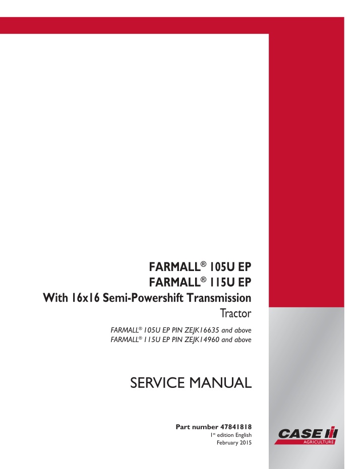
CASE IH FARMALL 105U EP With 16x16 Semi-Powershift Transmission Tractor Service Repair Manual Instant Download ( PIN ZEJK16635 and above)
CASE IH FARMALL 105U EP With 16x16 Semi-Powershift Transmission Tractor Service Repair Manual Instant Download ( PIN ZEJK16635 and above)
Download Presentation

Please find below an Image/Link to download the presentation.
The content on the website is provided AS IS for your information and personal use only. It may not be sold, licensed, or shared on other websites without obtaining consent from the author. If you encounter any issues during the download, it is possible that the publisher has removed the file from their server.
You are allowed to download the files provided on this website for personal or commercial use, subject to the condition that they are used lawfully. All files are the property of their respective owners.
The content on the website is provided AS IS for your information and personal use only. It may not be sold, licensed, or shared on other websites without obtaining consent from the author.
E N D
Presentation Transcript
FARMALL 105U EP FARMALL 115U EP With 16x16 Semi-Powershift Transmission Tractor FARMALL 105U EP PIN ZEJK16635 and above FARMALL 115U EP PIN ZEJK14960 and above SERVICE MANUAL Printed in U.S.A. Part number 47841818 1st edition English 2015 CNH Industrial Italia S.p.A. All Rights Reserved. Case IH is a trademark registered in the United States and many other countries, owned by or licensed to CNH Industrial N.V., February 2015 its subsidiaries or affiliates.
SERVICE MANUAL Farmall 105U EP with 16x16 Semi-Powershift transmission [ZEJK16635 - ] Farmall 115U EP with 16x16 Semi-Powershift transmission [ZEJK14960 - ] 47841818 24/02/2015 EN
Contents INTRODUCTION Engine....................................................................................... 10 [10.001] Engine and crankcase ............................................................. 10.1 [10.216] Fuel tanks .......................................................................... 10.2 [10.501] Exhaust Gas Recirculation (EGR) - Diesel Particulate Filter (DPF) exhaust treatment .................................................................................... 10.3 [10.414] Fan and drive ...................................................................... 10.4 Transmission.............................................................................. 21 [21.111] Semi-Powershift transmission...................................................... 21.1 [21.133] Semi-Powershift transmission external controls ................................... 21.2 [21.103] Semi-Powershift transmission lubrication system.................................. 21.3 [21.152] Semi-Powershift transmission internal components ............................... 21.4 [21.160] Creeper ............................................................................ 21.5 [21.118] Transmission/Rear drive ........................................................... 21.6 Four-Wheel Drive (4WD) system .................................................. 23 [23.202] Electro-hydraulic control ........................................................... 23.1 [23.314] Drive shaft.......................................................................... 23.2 Front axle system ....................................................................... 25 [25.100] Powered front axle ................................................................. 25.1 [25.102] Front bevel gear set and differential ............................................... 25.2 [25.108] Final drive hub, steering knuckles, and shafts ..................................... 25.3 Rear axle system........................................................................ 27 [27.100] Powered rear axle.................................................................. 27.1 [27.106] Rear bevel gear set and differential................................................ 27.2 [27.120] Planetary and final drives .......................................................... 27.3 [27.126] Spur gear and final drives.......................................................... 27.4 47841818 24/02/2015
https://www.ebooklibonline.com Hello dear friend! Thank you very much for reading. Enter the link into your browser. The full manual is available for immediate download. https://www.ebooklibonline.com
Power Take-Off (PTO)................................................................. 31 [31.104] Rear electro-hydraulic control...................................................... 31.1 [31.114] Two-speed rear Power Take-Off (PTO) ............................................ 31.2 [31.116] Three-speed rear Power Take-Off (PTO) .......................................... 31.3 [31.146] Front Power Take-Off (PTO) ....................................................... 31.4 Brakes and controls .................................................................... 33 [33.202] Hydraulic service brakes ........................................................... 33.1 [33.110] Parking brake or parking lock ...................................................... 33.2 [33.220] Trailer brake hydraulic control...................................................... 33.3 [33.224] Trailer brake pneumatic control .................................................... 33.4 [33.204] Front axle brake.................................................................... 33.5 Hydraulic systems....................................................................... 35 [35.000] Hydraulic systems.................................................................. 35.1 [35.104] Fixed displacement pump.......................................................... 35.2 [35.322] Regulated/Low pressure system................................................... 35.3 [35.204] Remote control valves ............................................................. 35.4 [35.114] Three-point hitch control valve ..................................................... 35.5 [35.162] Front hitch cylinders and lines ..................................................... 35.6 Hitches, drawbars, and implement couplings.................................. 37 [37.110] Rear three-point hitch .............................................................. 37.1 [37.162] Front hitch.......................................................................... 37.2 Steering..................................................................................... 41 [41.101] Steering control .................................................................... 41.1 [41.200] Hydraulic control components...................................................... 41.2 [41.216] Cylinders ........................................................................... 41.3 Cab climate control..................................................................... 50 [50.100] Heating............................................................................. 50.1 [50.200] Air conditioning..................................................................... 50.2 47841818 24/02/2015
Electrical systems....................................................................... 55 [55.000] Electrical system ................................................................... 55.1 [55.100] Harnesses and connectors......................................................... 55.2 [55.201] Engine starting system............................................................. 55.3 [55.301] Alternator........................................................................... 55.4 [55.302] Battery.............................................................................. 55.5 [55.640] Electronic modules................................................................. 55.6 [55.408] Warning indicators, alarms, and instruments ...................................... 55.7 [55.DTC] FAULT CODES.................................................................... 55.8 Platform, cab, bodywork, and decals............................................. 90 [90.150] Cab................................................................................. 90.1 [90.160] Cab interior trim and panels........................................................ 90.2 [90.100] Engine hood and panels ........................................................... 90.3 47841818 24/02/2015
INTRODUCTION 47841818 24/02/2015 1
Contents INTRODUCTION Capacities .......................................................................................3 47841818 24/02/2015 2
INTRODUCTION Capacities Fluid capacities and lubricant specifications approximate INTERNA- TIONAL SPECI- FICATION RECOMMENDED CASE IH PRODUCTS SPECIFICATION CASE IH Mixture of water and antifreeze CASE IH AKCELA PREMIUM ANTI-FREEZE at 50 % + 50 % - Cooling system: 16 l (4.2 US gal) MS1710 Windscreen wash reservoir - - 2 l (0.5 US gal) Water & cleaning liquid Decanted, filtered diesel fuel - - 165 l (43.6 US gal) Fuel tank: Engine sump: Minimum. 6.4 l (1.7 US gal) CASE IH AKCELA UNITEK NO. 1 SBL CJ-4 SAE 10W-40 or CASE IH AKCELA UNITEK NO. 1 SSL CJ-4 SAE 0W-40 CASE IH AKCELA LHM FLUID API CJ-4 ACEA E9 MAT3521 8.1 l (2.1 US gal) Maximum - 0.7 l (0.18 US gal) Brake control circuit ISO 7308 4.5 l (1.2 US gal) 1.0 l (0.3 US gal) Front axle: Final drives (each) Transmission Ring/Pinion Gears final drives and brakes ECM No. hydraulic lift torque of engine at power steering Front wheel hubs API GL4 ISO 32/46 SAE 10W-30 CASE IH AKCELA NEXPLORE FLUID MAT3525 63 l (16.6 US gal) - CASE IH AKCELA 251H EP MULTI-PURPOSE GREASE - NLGI 2 - Grease fittings Air-conditioning refrigerant Air-conditioning compressor oil - - 650 g (22.9 oz) R134 A - - 0.185 l (0.05 US gal) SP10 NOTICE: Avoid using fuel with sulfur content higher than 50 mg/kg ( 50 ppm or 0.005% ) 47841818 24/02/2015 3
SERVICE MANUAL Engine Farmall 105U EP with 16x16 Semi-Powershift transmission [ZEJK16635 - ] Farmall 115U EP with 16x16 Semi-Powershift transmission [ZEJK14960 - ] 47841818 24/02/2015 10
Engine - Engine and crankcase Engine - General specification GENERAL SPECIFICATIONS Engine, technical type: Farmall 105U Farmall 115U Engine rpm - high - nominal - low Cycle Fuel injection Number of cylinders in line Bore - All models Piston diameter Piston stroke Total displacement: - All models Compression ratio All models Maximum Power Output: Farmall 105U Farmall 115U Maximum power speed Peak torque Farmall 105U Farmall 115U Peak torque speed Torque increase Farmall 105U Farmall 115U Power at the power take off Farmall 105U Farmall 115U Number of main bearings Sump Lubrication Pump drive Oil filtration Engine oil pressure switch operating pressures: - contacts closing* with decreasing pressure. - contacts opening* with increasing pressure. * with the contacts closed the engine oil pressure warning light is on Cooling closing Capacity Fan with viscous joint, fixed to the specific pulley Coolant pump Coolant thermometer Temperature ranges corresponding to each section: initial dark blue sector final red sector dark blue area Start of opening Timing 4 Cylinders F5DFL413B*A006 F5DFL413B*A002 2400 - 2500 RPM 2300 RPM 700 - 800 RPM diesel, 4-stroke Direct 4 99 mm (3.8976 in) 110 mm (4.3307 in) 3400 cm 17 0.5 : 1 79 kW (107 Hp) 84 kW (114 Hp) 2300 RPM 444 N m (327.48 lb ft) 461 N m (340.02 lb ft) 1500 RPM 35 % 32 % 68.6 kW (93.3 Hp) 73.9 kW (100.4 Hp) 5 structural, cast iron forced, with lobe pump from crankshaft mesh screen on oil intake and filter cartridge on delivery line 0.2 bar (2.90 psi) 0.9 bar (13.05 psi) coolant circulation with five rows of vertical pipes 16 l (4.23 US gal) 520 mm (20.4724 in) intake, in plastic with 10 blades colored scale divided into three sections normal temperature high temperature via thermostat valve 80 C (176.00 F) overhead valves operated by tappets, rods and rocker arms via the camshaft located in the engine block; the camshaft is driven by the crankshaft using straight-tooth gears 47841818 24/02/2015 10.1 [10.001] / 3
Engine - Engine and crankcase GENERAL SPECIFICATIONS 4 Cylinders Intake: start: before P.M.S. end: after P.M.I. Exhaust: start: before P.M.I. end: after P.M.S. Clearance between valves and rocker arms with engine cold. Turbocharging Air cleaning 19 37 61 21 The valve clearance is hydraulically controlled. Therefore, manual adjustment is not necessary. Turbocharged with intercooler dual cartridge dry air cleaner, with clogged filter indicator with centrifugal pre-filter and automatic dust ejector by mesh prefilter on the supply pipe, suction line filter with water - fuel separator, low pressure filter and sensor. Manual mounted on the suction line filter BOSCH High pressure Common Rail control unit HPCR - CP4.1 Electro-injectors 300 - 1400 bar (4350.00 - 20300.00 psi) Fuel filtration Priming pump Injection pump Type Nozzles type Injection pressure Filling: Engine sump Fuel tank Anti-pollution system Type: 6.4 - 8.1 l (1.69 - 2.14 US gal) 140 l (36.98 US gal) Exhaust gas recycling system EGR Particulate filter DPF* every 3000 hours Recommended frequency for renewing filter NOTE: * - For filter maintenance please refer to: ( Diesel Particulate Filters (DPF) - Dynamic description manual regeneration of the diesel particulate filter (DPF) (55.408)) 47841818 24/02/2015 10.1 [10.001] / 4
Engine - Engine and crankcase Engine - Remove 1. Remove the engine hood (1), as indicated in Hood - Remove (90.100). 2. Open the lock (1) to release the lower steps of the lad- der. Removethebatterycover(2). Disconnecttheneg- ative cable of the battery. 1 MOIL12TR00670AA 3. Remove the cotter pins, retaining pin, and the complete front ballasts (1) from the relative support. 2 WLAPL4S10C102AA 4. Loosen the retaining screws (1). fenders (2) from both sides (if present). Remove the front 3 WLAPL4S10C104A 5. Remove the retaining screws (1). Remove the left- hand engine side panel (2). Perform the same opera- tion for the right-hand side panel. Remove the storage compartment. 4 WLAPL4S10C105A 47841818 24/02/2015 10.1 [10.001] / 5
Engine - Engine and crankcase 6. Use the special tool 380000315 to recover the refrig- erant liquid from the system via the fittings (1) and (2). Remove the tube (1). Clear the section of brackets and clamps. Move the tube onto the capacitor ( (1), 6). Re- move the tube (2). Clear the section. Move the tube onto the cab. 5 WLAPL4S10C106AA 7. At the front of the engine, remove the lower tube (3) on the capacitor (1). Free the tube from any straps or clamps. Disconnect the sensor (2). Move the tube onto the cab. 6 WLAPL4S10C107A 8. Raise the rear of the tractor with a hydraulic jack. Place a mechanical jack stand under the reduction gear box. Use a pneumatic gun to remove the retaining nuts of the left-hand rear wheel. Then remove the wheel. 7 WLAPL4S10C110A 9. Loosen the front, central, and rear retaining screws of the curtain (1) of the front axle control shaft. Remove the curtain. 8 WLAPL4S10C112AA 47841818 24/02/2015 10.1 [10.001] / 6
Engine - Engine and crankcase 10. Remove the circlip (2). Move the front sleeve (1) in the direction indicated by the arrow in order to release the sleeve from the groove on the front axle. 9 WLAPL4S10C113AA 11. Remove the screws that secure the central support (1) from the drive shaft. Retrieve the shaft together with the support. Retrieve the shim that adjusts the clearance of the shaft on the back. 10 WLAPL4S10C115AA 12. Loosen the inlet of the water return line from the cab heater radiator. Drain and retrieve the engine coolant. 11 WLAPL4S10C116A 13. Remove the cap (1). Drain the oil from the transmis- sion box. 12 MOIL13TR00197AA 47841818 24/02/2015 10.1 [10.001] / 7
Engine - Engine and crankcase 14. Loosen the device that fastens the muffler to the ex- haust pipe. Free the exhaust pipe from any cab sup- port fastening brackets. Loosen the connection to the DPF filter. Then remove the exhaust pipe. 13 WLAPL4S10C118A 15. Loosen the fixing clamps (1). Extract the tubing from the turbine to the radiator intercooler (2). Perform the same operation for the tubing from the radiator inter- cooler to the engine (3). 14 WLAPL4S10C119A 16. Loosen the clamp (2) that joins the air inlet duct to the turbine. Release the air filter (4), together with the bracket (3), from the retaining screws. On the left-hand side of the engine, disconnect the oil vapor duct (1) from the fuel pump. 15 WLAPL4S10C120A 17. Release the air filter support (1) from the retaining screws. Remove the air filter support. 16 WLAPL4S10C121A ATTENTION: The DPF (1) filter outlet union has a decoupler at the end (2). The decoupler only responds to temper- ature variations longitudinally. 47841818 24/02/2015 10.1 [10.001] / 8
Engine - Engine and crankcase A small misalignment of the axis of the decoupler with respect to the axis of the turbine outlet (3) would produce an adjustment that would no longer be longitudinal, in line with the direction of the tractor. This small misalignment would produce an abnormal transversal adjustment, which would affect its durability. 18. Disconnect all of the filter sensors. Loosen the clamp (4). Loosen the four screws (5) that secure the filter to the bottom support to remove the filter together with the sensors and heat shields. 17 WLAPL4S10C122A ATTENTION: Only if you have to work on the parts under- neath the DPF filter support, it is advisable to remove the support. When possible, you should remove the upper part (1) and the right-hand part (2) as a block. To do this, remove the retaining screws (3) on the right-hand side of the engine. (These screws work on a vertical slot, so that the support (2) can have various height positions.) Before disassem- bly, it is necessary to take some references of the position on the engine, so that you can return the block to the orig- inal position during reassembly. 18 WLAPL4S10C123A 19. To remove the rear shield, loosen the two screws that fix the support (4) to the support (1). To remove the left-hand support (5), loosen the two retaining screws on the left-hand bracket (1). Retrieve the respective centering bushings. 19 WLAPL4S10C124A 20. Disconnect the steering control lines (1) and (2). Dis- connect the oil supply line to the distributor (3). Remove the fastening (4) of the engine lines. 20 WLAPL4S10C125A 47841818 24/02/2015 10.1 [10.001] / 9
Engine - Engine and crankcase 21. Disconnect the exhaust pipe (2) of the power-steering control valve. Disconnect the power supply line (1) of the transmission control valve. Then remove the filter (3) together with the support. 21 WLAPL4S10C126A 22. Disconnect the inlet pipes from the pump (1). Discon- nect the inlet pipe (2) from the transmission oil filter, at the height of the cab support. Disconnect the supply line to the lift (3). Disconnect the supply lines (5) to the lift and to the power-steering anti-cavitation tank (6). 23. Remove the filter assembly (4) together with the tank (6), support, and parts of the tubing that were previ- ously disconnected. 24. Remove the power-steering pump assembly from the high-pressure circuit. 22 WLAPL4S10C127A 25. Remove the tubes of the heat exchanger (1), differen- tial lock (3), and (if applicable) front braking assembly (4). 26. Release the lines that were previously disconnected from the supports, brackets, and clamps secured to the engine. Do the same for the lines directed to the steering cylinder (2). 23 WLAPL4S10C128A 27. On the right-hand side of the engine, disconnect the cab heating lines (1). Disconnect the tubing from the expansion tank that is inserted on the engine sleeve (3). Loosen the clamps. On the engine, disconnect the connecting rubber sleeves (4) of the radiator. 24 WLAPL4S10C134A 47841818 24/02/2015 10.1 [10.001] / 10
Engine - Engine and crankcase 28. On the right-hand side, remove the guard (1) on the starter motor (2). Disconnect the starter cable and battery isolator. Disconnect the alternator and the re- spective connecting cable. Release all of the wiring from the fixing clamps. 29. Loosen the fastening (3). Remove the ground con- nection cable. Remove starter 25 WLAPL4S10C135A 30. On the FTP interface cable (1) with the motor, discon- nect all of the connections (2), except for the connec- tions on the maxi fuse compartment and on the glow plug controller. After you cut the fixing clamps, recon- nect the cable on the front near the controller (5). 31. On the main engine cable (3), disconnect the con- nectors from the controller (4) including the maxi fuse compartment, switches, and sensors positioned on the engine. After you cut the fixing clamps, move the cable onto the rear of the engine at the height of the right-hand ladder. 26 WLAPL4S10C137A 32. On the left-hand side, disconnect the cab power ca- ble connector (1). Release the connector from the clamps. Move the connector onto the maxi fuse com- partment. 33. Remove the bracket (2) of the cab electrical connec- tors, cab electrical supply, and cup filter (3). Discon- nect the tubing that joins the cup filter to the mechan- ical priming pump on the sediment filter. 27 WLAPL4S10C139A 34. Hook the rear part of the engine to a hoist using chains or ropes for lifting. (Apply two eyebolts, one to the right-hand side and one to the left-hand side, on the upper part of the flange containing the flywheel.) Po- sition a fixed jack stand (2) under the clutch case (1) near the engine attachment flanging. 28 WLAPL4S10C129A 47841818 24/02/2015 10.1 [10.001] / 11
Engine - Engine and crankcase 35. Position the movable tractor splitting tool 380003114 (2) with the support bracket and adapter plate under the engine. Place a wooden block (1) at the points of contact between the tool and the engine. Wedge the axle to prevent swinging. 29 WLAPL4S10C140A 36. Remove the retaining bolts (1) between the engine and the transmission. 30 WLAPL4S10C130A 37. Separate the engine (1) from the transmission with the tool 380003114 (2). 31 WLAPL4S10C131AA 38. Insert the fixed jack stand (1) under the ballast sup- port. Chock the front wheels with wooden blocks (2). 32 WLAPL4S10C132AA 47841818 24/02/2015 10.1 [10.001] / 12
Engine - Engine and crankcase 39. Position a fixed jack stand (3) under the support of the groove(1)ofthepowertake-offofthefrontaxle. Insert a wooden plug between parts (3) and (1). 33 WLAPL4S10C133A 40. Position a jack stand under the rear of the engine in order to be able to safely release the hoist with the coupling device. Add a rope or chain also on the front of the engine. Take up the slack with the lifting device. Keep the engine balanced. 34 WLAPL4S10C136A 41. Remove the screws (1) that secure the front axle sup- port (2) to the engine. Retrieve the adjuster spacers of the engine block (4) or sump (3). 35 WLAPL4S10C141A 42. Check that there are no brackets between the engine and the cooling assembly. Remove the engine (2) from the front axle (3). Try to avoid incorrect engine maneuvers in order to not damage the fins or the ra- diator (1) on the axle. Then rest the engine (2) on a suitable support. 36 WLAPL4S10C138A 47841818 24/02/2015 10.1 [10.001] / 13
Engine - Engine and crankcase 43. Remove the viscous coupling (1), if applicable, to- gether with the fan (2). 37 WLAPL4S10C144A 44. Loosen the supercharger retaining screws (4). Re- move the belt (5). Then remove the supercharger. 45. Completely loosen the belt tensioner (2). Remove the elastic belt (3). Then remove the alternator (1). 38 WLAPL4S10C145A 47841818 24/02/2015 10.1 [10.001] / 14
Suggest: If the above button click is invalid. Please download this document first, and then click the above link to download the complete manual. Thank you so much for reading
Engine - Engine and crankcase Engine - Install 1. - Refit the flexible belt on the alternator and take up the slack according to the procedure in Accessory belt - Tension adjust (10.414). 2. - Reposition the compressor and the relevant belt fol- lowing this procedure: - Put the compressor back on the support and with the related pipe support. Secure with the bolts To fit the polyv belt, use tool 380200011. (1). Compressor clutch actuator drive bracket. (2). Outer edge of polyv belt pulley. (3). Tool recess. Used to drive the tool. This recess houses the bracket (1). (4). Tail. Used to drive the polyv belt in the pulley seat. (5). Hitching. Thanks to this recess, where the outer edge(2)ishoused, thetoolremainshitchedtothecom- pressor. 1 WLAPL4S10C101C 47841818 24/02/2015 10.1 [10.001] / 15
https://www.ebooklibonline.com Hello dear friend! Thank you very much for reading. Enter the link into your browser. The full manual is available for immediate download. https://www.ebooklibonline.com

