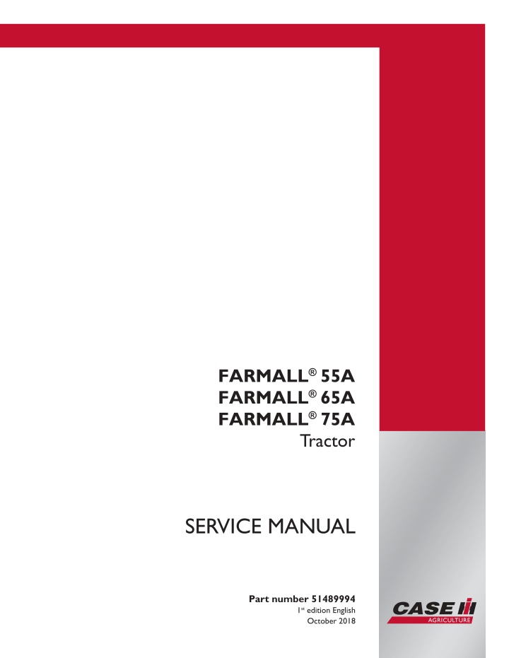
CASE IH FARMALL 55A Tractor Service Repair Manual Instant Download
CASE IH FARMALL 55A Tractor Service Repair Manual Instant Download
Download Presentation

Please find below an Image/Link to download the presentation.
The content on the website is provided AS IS for your information and personal use only. It may not be sold, licensed, or shared on other websites without obtaining consent from the author. If you encounter any issues during the download, it is possible that the publisher has removed the file from their server.
You are allowed to download the files provided on this website for personal or commercial use, subject to the condition that they are used lawfully. All files are the property of their respective owners.
The content on the website is provided AS IS for your information and personal use only. It may not be sold, licensed, or shared on other websites without obtaining consent from the author.
E N D
Presentation Transcript
FARMALL55A FARMALL 65A FARMALL 75A Tractor SERVICE MANUAL Printed in U.S.A. Part number 51489994 1st edition English 2018 CNH Industrial Italia S.p.A. All Rights Reserved. Case IH is a trademark registered in the United States and many other countries, owned by or licensed to CNH Industrial N.V., October 2018 its subsidiaries or affiliates.
Contents Maintenance .............................................................................. 00 [00.100] New unit pre-delivery operations................................................... 00.1 [00.150] Start-up............................................................................. 00.2 Engine....................................................................................... 10 [10.001] Engine and crankcase ............................................................. 10.1 Clutch ....................................................................................... 18 [18.110] Clutch and components ............................................................ 18.1 Transmission.............................................................................. 21 [21.114] Mechanical transmission ........................................................... 21.1 [21.112] Power shuttle transmission......................................................... 21.2 Four-Wheel Drive (4WD) system .................................................. 23 [23.101] Mechanical control ................................................................. 23.1 [23.304] Four-Wheel Drive (4WD) gearbox ................................................. 23.2 Front axle system ....................................................................... 25 [25.100] Powered front axle ................................................................. 25.1 Rear axle system........................................................................ 27 [27.100] Powered rear axle.................................................................. 27.1 Power Take-Off (PTO)................................................................. 31 [31.101] Rear mechanical control ........................................................... 31.1 [31.104] Rear electro-hydraulic control...................................................... 31.2 [31.114] Two-speed rear Power Take-Off (PTO) ............................................ 31.3 Brakes and controls .................................................................... 33 [33.202] Hydraulic service brakes ........................................................... 33.1 Hydraulic systems....................................................................... 35 [35.000] Hydraulic systems.................................................................. 35.1 51489994 09/10/2018
[35.116] Three-point hitch cylinder .......................................................... 35.2 [35.204] Remote control valves ............................................................. 35.3 Steering..................................................................................... 41 [41.101] Steering control .................................................................... 41.1 [41.200] Hydraulic control components...................................................... 41.2 [41.216] Cylinders ........................................................................... 41.3 Cab climate control..................................................................... 50 [50.100] Heating............................................................................. 50.1 [50.200] Air conditioning..................................................................... 50.2 Electrical systems....................................................................... 55 [55.000] Electrical system ................................................................... 55.1 [55.051] Cab Heating, Ventilation, and Air-Conditioning (HVAC) controls................... 55.2 [55.100] Harnesses and connectors......................................................... 55.3 [55.201] Engine starting system............................................................. 55.4 [55.301] Alternator........................................................................... 55.5 [55.302] Battery.............................................................................. 55.6 [55.408] Warning indicators, alarms, and instruments ...................................... 55.7 [55.512] Cab controls........................................................................ 55.8 [55.DTC] FAULT CODES.................................................................... 55.9 Front loader and bucket............................................................... 82 [82.100] Arm................................................................................. 82.1 [82.300] Bucket.............................................................................. 82.2 [82.AAA] Front loader and bucket generic sub-group ....................................... 82.3 Platform, cab, bodywork, and decals............................................. 90 [90.150] Cab................................................................................. 90.1 51489994 09/10/2018
https://www.ebooklibonline.com Hello dear friend! Thank you very much for reading. Enter the link into your browser. The full manual is available for immediate download. https://www.ebooklibonline.com
SERVICE MANUAL Engine FARMALL 55A FARMALL 65A FARMALL 75A 51489994 09/10/2018 10
Engine - Engine and crankcase Engine and crankcase - Disassemble ENGINE Removal ATTENTION: Use appropriate equipment to hold and lift heavy parts. Make sure that that the body and parts are safely supported safely by ropes and hooks. Make sure that no one is close when you lift heavy loads. ATTENTION: Use appropriate tools to align holes on parts. NEVER USE YOUR FINGERS OR HANDS Follow these steps. 1. To access the engine, remove the protective covers (1) on either side. Remove the cover retaining bolts (2) and remove the side covers. 1 ANIL17TRO0925AA 2. Use the A/C device (1) to discharge the gas in the sys- tem. For this, use the A/C device pressure hose (red) and connect to the compressor s red bushing. Connect the blue hose to the compressor s blue bushing. 2 ANIL17TRO0926AA 3. Disconnect the battery terminals (1). 3 ANIL17TRO0927AA 51489994 09/10/2018 10.1 [10.001] / 4
Engine - Engine and crankcase 4. Engage the handbrake. Remove the engine oil drain plug (1) on both side. 4 ANIL18TRO1093AA 5 ANIL18TRO1092AA 5. Remove the front weight connection rod (1). 6 ANIL17TRO0992AA 6. Remove the front weight lower connection rod (1). 7 ANIL17TRO0930AA 51489994 09/10/2018 10.1 [10.001] / 5
Engine - Engine and crankcase 7. Remove the front weights (1). 8 ANIL17TRO0931AA 8. (1)Use the specific tool to discharge the refrigerant from the system via the greasers and (2). Remove the bracket strips and separate the two lines. 380000315 . 9 ANIL1800789AA 9. Disconnect lines (1) and (2) of the cab A/C and heating (if any). 10 MOIL13TR02884AA 51489994 09/10/2018 10.1 [10.001] / 6
Engine - Engine and crankcase 10. Separate the supply and return pipes for the (1) trans- missioncoolingoilattheconnectionpoint. Disconnect the hoses from the supports on the engine block. . 11 MOIL13TR02886AB 11. Lift the rear of the tractor with a hydraulic jack. Place a mechanical jack under the crawl speed gear housing. Use an air gun to remove the retaining nuts on the left rear wheel. Then remove the wheel. 12 WLAPL4S10C110A 12. Removethefrontcenterandrearretainingboltsonthe front wheel drive control shaft housing. Then remove the guard. (1). 13 WLAPL4S10C112AA 13. Remove the retaining ring (2). Move the front screen in the direction of the arrow (1) to remove the screen from the grooves on the front axle. 14 WLAPL4S10C113AA 51489994 09/10/2018 10.1 [10.001] / 7
Engine - Engine and crankcase 14. Remove the retaining bolts of the middle bracket of the drive shaft (1). Remove the shaft and the bracket. Remove the adjustment washer that adjusts the shaft space behind. 15 WLAPL4S10C115AA 15. Loosen the strips. Separate the suction hose (1) that goes to the oil filter from the transmission (2). 16 MOIL13TR02887AB 16. For machines with a hydraulic lifter and middle mounted valves, remove the oil feed pipe to the distributor of the lifting device and oil filter (1) . 17 ANIL18TRO1094AA 17. Disconnect all electrical connections that prevent the engine from being removed from the gearbox trans- mission housing. For example, the main connections (1), the main cab and power connections (2), the en- gine control unit connections (3), the fuse box (4), the sensors, and the extensions, depending on the tractor model. 18 MOIL13TR02889AB 51489994 09/10/2018 10.1 [10.001] / 8
Engine - Engine and crankcase 18. Remove the retaining bolts (1). Remove the top ra- diator guard (2). Remove all the remaining free wire bundles. .. 19 MOIL13TR02942AA 19. Loosen the strip on the inlet of the hose (1) that feeds fluid to the radiator. Disconnect the hose. Drain the engine radiator fluid and refill with fluid. 20. Remove the retaining strip. Hose (2) that returns the radiator fluid to the engine. 20 ANIL18TRO1099AA 21. Loosen the strip. Disconnect the hose (1) that runs from the air filter to the turbine. Next, remove the two bolts (3) and remove the bracket (2). 21 MOIL13TR02890AB 51489994 09/10/2018 10.1 [10.001] / 9
Engine - Engine and crankcase 22. Loosen the strip (1). Remove the hose (2) that con- nects the air filter to the injection pump. . 22 MOIL13TR02891AB 23. Disconnect the hydraulic steering hoses (1). Discon- nect the lines from the axle bracket. . 23 MOIL13TR02881AB 24. Unplug the headlamp and the signal cable bundle from the engine hood socket (1). 24 ANIL1898734AA 25. Attach chains or ropes to the lifting and eye bolts be- hind the engine and attach to a winch. Place a fixed lifting jack (2) under the clutch body (1) next to the en- gine retaining flange. Apply the handbrake. . 25 WLAPL4S10C129A 51489994 09/10/2018 10.1 [10.001] / 10
Engine - Engine and crankcase 26. Place the moving tractor separator tool (2) under the engine with the mounting bracket and the adapter plate. Place a wooden block (1) at the points of con- tact between the tool and the motor. Chock the axle to prevent the axle from shaking. 380000405. . 26 WLAPL4S10C140A 27. Remove the retaining bolts (1) between the engine and the transmission. 27 WLAPL4S10C130A 28. Separate the engine from the transmission with tool 380000405 (2). 380000405. 28 WLAPL4S10C131AA 29. Place the fixed lifting jack (1) under the additional weight support. Use wooden blocks (2) to secure the front wheels. . 29 WLAPL4S10C132AA 51489994 09/10/2018 10.1 [10.001] / 11
Engine - Engine and crankcase 30. Place a wooden stop between parts (3) and (1). Place a fixed lifting jack (3) under the front axle drive groove (1) bracket. 30 WLAPL4S10C133A 31. With the connection assembly firmly secure, place a lifting jack at the rear of the engine to leave slack in the winch. Add a rope or chain to the front of the engine (1). Keep the engine balanced and take the slack out of the lifting assembly. 32. Remove the bolts that secure the front axle bracket to the engine (2). 31 WLAPL4S10C136A 33. Check that there is no elbow between the engine and the radiator. Separate the engine (2) from the axle (3). To prevent damage to the fins of the radiator on the engine ventilator (1) axle, try to avoid incorrect manoeuvreswiththewinch. Lowertheengine(2)onto a support bracket. 32 WLAPL4S10C138A 34. Loosen the four bolts (1). Remove the fan (2). 33 MOIL13TR02885AA 51489994 09/10/2018 10.1 [10.001] / 12
Engine - Engine and crankcase Engine and crankcase - Install 1. Reattach the flexible strap to the alternator and take the tension according to the procedure in the Alternator - Tension adjust (55.301) section. 2. Repeat this operation to reposition the compressor and the corresponding belt. - Put the compressor on the bracket together with the relevant hose bracket. Secure with the bolts. - - Use tool 380200011 to install the multi-V belt. (1)The drive bracket of the compressor clutch actuator. (2)Outer edge of the multi-V belt pulley. (3)Tool space. Use to drive the tool. The bracket (1) is housed in this space (4) Tail end. The multi-V belt drives the pulley socket. (5) Coupling. This space around the outer edge (2) allows the tool to remain connected to the compressor. (2). 1 WLAPL4S10C101C 51489994 09/10/2018 10.1 [10.001] / 13
Engine - Engine and crankcase 3. Removethethreebolts(1). Removethecorresponding dust cover for the compressor clutch. 2 WLAPL4S10C142A 4. Makesurethatthemulti-Vbelt(2)isproperlypositioned in the ventilator pulley. 5. Move the belt (2) to the side of the compressor pul- ley.Hold tool 380200011 under the belt. Hook the com- pressor clutch from the innermost part of the tool to slightly stretch the belt. 3 WLAPL4S10C143A 6. With your left hand on the ventilator and your right hand on the tool, turn both clockwise to move the belt along the compressor pulley. Replace the dust cap on the compressor clutch. To prevent loosening, make sure that locking film covers the ends and tighten the three screws. 7. Position the alternator (1) and elastic belt (3). Tighten the belt tensioner (2). 4 WLAPL4S10C145A 8. Position the ventilator (2). (1) Tighten the four screws to the correct torque value. 5 MOIL13TR02885AA 51489994 09/10/2018 10.1 [10.001] / 14
Engine - Engine and crankcase 9. Place the three hooks of the chain in the holes on the engine. Use a winch to lift the engine completely from the platform bracket. 10. Position the engine (2) on the front axle. (3). To pre- vent damage to the fins of the radiator on the engine ventilator, try to avoid incorrect manoeuvres with the winch. (1). Then combine the two components with the special adjustment bolts and the necessary adjustment spac- ers of the sump/cylinder block bracket. 6 WLAPL4S10C138A 11. Reposition the moving tool under the engine to disas- semblethetractors(2).Placeawoodenblockbetween the contact points of the tool (1) and engine. 7 WLAPL4S10C140A 12. With a winch, position the engine (1) on the tool (2). Remove the bolts attached previously to the rear of the engine for the purposes of lifting. 8 WLAPL4S10C131AA 13. Remove the fixed lifting jack (3) and the wooden wedge (2) previously positioned under the groove bracket of the front axle drive shaft (1). (2). 9 WLAPL4S10C133A 51489994 09/10/2018 10.1 [10.001] / 15
Engine - Engine and crankcase 14. Remove the fixed lifting jack (1) previously placed un- der the additional weight bracket. Remove the chocks (2) that secure the front wheels. (2) 10 WLAPL4S10C132AA 15. Remove the sealant from the two surfaces of the en- gine and housing. 16. Apply LOCTITE 518 and sealant to the matching surfaces of the motor and the clutch housing. 17. Place a wooden chock under the right rear wheel. Make sure that the handbrake is fully applied and that all fixed and movable stands are securely positioned. 18. The assembly phase described here requires the presence of two or three workers to use the special moving tool needed to dismantle the tractor, and to move the engine/front axle housing towards the gearbox housing. 19. When you mount the engine/front axle assembly to the gearbox housing, push the front wheels to prevent the hoses and the cables/electrical connections being trapped between the two parts. In this phase you also need to turn the crankshaft with the radiator cooling fan to help establish a connection between the sleeve and the drive shaft. 20. Tighten all the retaining bolts (1) that connect the en- gine to the gearbox housing to connect the two as- semblies. (1) 11 WLAPL4S10C130A 51489994 09/10/2018 10.1 [10.001] / 16
Engine - Engine and crankcase 21. Remove the winch chains. Remove the lifting jack (1) previously positioned under the clutch housing (2). Removethemovingtoolusedtodisassemblethetrac- tors. 12 WLAPL4S10C129A 22. Reinstall the support bracket (2) of the cab connectors (1), the cab electrics, and the cup filter (3). the mechanical diesel automator connection on the sediment filter of the cup filter. Connect 23. Connect the cab electrical cable connector (1) on the left side. Put the connector on the maxi fuse box and fasten with the cuffs. 13 WLAPL4S10C139A 24. Lay the FPT engine cable on the machine. Reconnect the various connections. Secure the cables with the cuffs. Reconnectthemainelectricalconnections(1), thecab connections and power (2), the engine control unit connections (3), the fuse section (4) and connections, the sensors, and the extensions, depending on the tractor model. 14 MOIL13TR02889AB 25. Reattach the starter motor (2). engine chassis cable and battery system. Secure the chassis cable with the bolt (3). Then connect the 26. On the right-hand side, reconnect the positive battery cable and wiring harness to the starter motor and al- ternator. Put the cover (1) back onto the starter motor (2). 15 WLAPL4S10C135A 51489994 09/10/2018 10.1 [10.001] / 17
Suggest: If the above button click is invalid. Please download this document first, and then click the above link to download the complete manual. Thank you so much for reading
Engine - Engine and crankcase 27. Reinstall the two feed and return pipes to the cab heater (1) and the hose (3) from the expansion tank, which is attached to the bottom sleeve. 16 MOIL13TR01739AB 28. Installandconnectthehydraulicsteering(1). Secure the hydraulic steering lines to the front axle bracket. 17 MOIL13TR02881AB 29. Connect the hose (2) that connects the air filter to the injection pump. Tighten the strip to secure the hose. (1). 18 MOIL13TR02891AB 30. Connect the hose that runs from the air filter to the turbine. Tighten the strip to secure the hose. (1) .- - Also reattach the hood bracket (2). two bolts (3) to secure the hood bracket. Tighten the 19 MOIL13TR02890AB 51489994 09/10/2018 10.1 [10.001] / 18
https://www.ebooklibonline.com Hello dear friend! Thank you very much for reading. Enter the link into your browser. The full manual is available for immediate download. https://www.ebooklibonline.com








![Comprehensive Case Study on [Insert Case Title Here]](/thumb/159705/comprehensive-case-study-on-insert-case-title-here.jpg)
