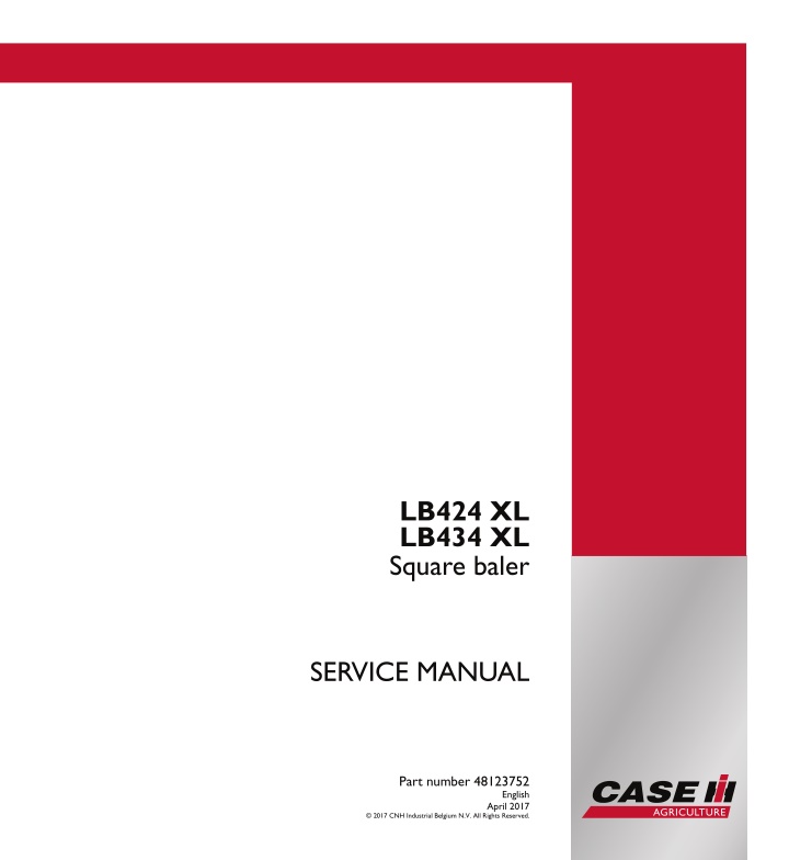
CASE IH LB424 XL Square baler Service Repair Manual Instant Download
CASE IH LB424 XL Square baler Service Repair Manual Instant Download
Download Presentation

Please find below an Image/Link to download the presentation.
The content on the website is provided AS IS for your information and personal use only. It may not be sold, licensed, or shared on other websites without obtaining consent from the author. If you encounter any issues during the download, it is possible that the publisher has removed the file from their server.
You are allowed to download the files provided on this website for personal or commercial use, subject to the condition that they are used lawfully. All files are the property of their respective owners.
The content on the website is provided AS IS for your information and personal use only. It may not be sold, licensed, or shared on other websites without obtaining consent from the author.
E N D
Presentation Transcript
SERVICE MANUAL LB424 XL LB434 XL Square baler LB424 XL LB434 XL Square baler Part number 48123752 1/2 SERVICE MANUAL Part number 48123752 English April 2017 2017 CNH Industrial Belgium N.V. All Rights Reserved.
SERVICE MANUAL LB424R XL Rotor Cutter LB424S XL Standard LB434R XL Rotor Cutter LB434S XL Standard 48123752 21/03/2017 EN
Contents INTRODUCTION Power Take-Off (PTO)................................................................. 31 [31.201] Power Take-Off (PTO) drive shaft.................................................. 31.1 [31.205] Flywheel............................................................................ 31.2 [31.220] Gearbox............................................................................ 31.3 [31.225] Clutches............................................................................ 31.4 Brakes and controls .................................................................... 33 [33.202] Hydraulic service brakes ........................................................... 33.1 [33.300] Pneumatic service brakes.......................................................... 33.2 Hydraulic systems....................................................................... 35 [35.540] Bale density circuit ................................................................. 35.1 [35.568] Knife positioning circuit............................................................. 35.2 [35.570] Bale eject circuit.................................................................... 35.3 [35.580] Rear bale chute positioning system................................................ 35.4 [35.585] Tandem auto-steer lock circuit ..................................................... 35.5 Electrical systems....................................................................... 55 [55.000] Electrical system ................................................................... 55.1 [55.100] Harnesses and connectors......................................................... 55.2 [55.629] Pressing/Bale formation electrical control.......................................... 55.3 [55.640] Electronic modules................................................................. 55.4 [55.633] Baler feeding control ............................................................... 55.5 [55.629] Pressing/Bale formation electrical control.......................................... 55.6 [55.433] Twine and net cutting and tying or wrapping....................................... 55.7 [55.408] Warning indicators, alarms, and instruments ...................................... 55.8 [55.DTC] FAULT CODES.................................................................... 55.9 Product feeding.......................................................................... 60 48123752 21/03/2017
https://www.ebooklibonline.com Hello dear friend! Thank you very much for reading. Enter the link into your browser. The full manual is available for immediate download. https://www.ebooklibonline.com
[60.220] Pickup.............................................................................. 60.1 [60.260] Rotor ............................................................................... 60.2 [60.230] Precompression.................................................................... 60.3 [60.240] Packer.............................................................................. 60.4 [60.280] Stuffer .............................................................................. 60.5 Pressing - Bale formation............................................................. 62 [62.100] Plunger and connecting rod........................................................ 62.1 Tying/Wrapping/Twisting.............................................................. 68 [68.160] Knotter frame....................................................................... 68.1 [68.100] Knotter drive system ............................................................... 68.2 [68.110] Knotter clutch and brake ........................................................... 68.3 [68.130] Needles ............................................................................ 68.4 [68.120] Knotter trip mechanism ............................................................ 68.5 [68.140] Knotter stack ....................................................................... 68.6 Ejection..................................................................................... 70 [70.250] Bale chute.......................................................................... 70.1 Lubrication system...................................................................... 71 [71.460] Grease lubrication system ......................................................... 71.1 [71.480] Oiler system........................................................................ 71.2 Platform, cab, bodywork, and decals............................................. 90 [90.105] Machine shields and guards ....................................................... 90.1 48123752 21/03/2017
INTRODUCTION 48123752 21/03/2017 1
INTRODUCTION Basic instructions - How to use and navigate through this Manual Large LB series ANZ --- APAC --- MEA --- WE Technical information This manual has been produced by a new technical information system. This new system is designed to deliver technical information electronically through Web delivery (eTim), DVD and in paper manuals. A coding system called SAP has been developed to link the technical information to other Product Support functions, e.g., Warranty. Technical information is written to support the maintenance and service of the functions or systems on a customer's machine. When a customer has a concern on his machine it is usually because a function or system on his machine is not working at all, is not working efficiently, or is not responding correctly to his commands. When you refer to the technical information in this manual to resolve that customer's concern, you will find all the information classified using the SAP coding, according to the functions or systems on that machine. Once you have located the technical information for that function or system then you will find all the mechanical, electrical or hydraulic devices, compo- nents, assemblies and sub assemblies for that function or system. You will also find all the types of information that have been written for that function or system, the technical data (specifications), the functional data (how it works), the diagnostic data (fault codes and troubleshooting) and the service data (remove, install adjust, etc.). By integrating SAP coding into technical information, you will be able to search and retrieve just the right piece of technical information you need to resolve that customer's concern on his machine. This is made possible by attaching 3 categories to each piece of technical information during the authoring process. The first category is the Location, the second category is the Information Type and the third category is the Product: LOCATION - is the component or function on the machine, that the piece of technical information is going to describe e.g. Fuel tank. INFORMATION TYPE - is the piece of technical information that has been written for a particular component or function on the machine e.g. Capacity would be a type of Technical Data that would describe the amount of fuel held by the Fuel tank. PRODUCT - is the model for which the piece of technical information is written. Every piece of technical information will have those 3 categories attached to it. You will be able to use any combination of those categories to find the right piece of technical information you need to resolve that customer's concern on his machine. That information could be: the description of how to remove the cylinder head a table of specifications for a hydraulic pump a fault code a troubleshooting table a special tool 48123752 21/03/2017 3
INTRODUCTION How to use this manual This manual is divided into Sections. Each Section is then divided into Chapters. Contents pages are included at the beginning of the manual, then inside every Section and inside every Chapter. An alphabetical Index is included at the end of a Chapter. Page number references are included for every piece of technical information listed in the Chapter Contents or Chapter Index. Each Chapter is divided into four Information types: Technical Data (specifications) for all the mechanical, electrical or hydraulic devices, components and, assemblies. Functional Data (how it works) for all the mechanical, electrical or hydraulic devices, components and assemblies. Diagnostic Data (fault codes, electrical and hydraulic troubleshooting) for all the mechanical, electrical or hydraulic devices, components and assemblies. Service Data (remove disassembly, assemble, install) for all the mechanical, electrical or hydraulic devices, com- ponents and assemblies. Sections Sections are grouped according to the main functions or a systems on the machine. Each Section is identified by a number 00, 35, 55, etc. The amount of Sections included in the manual will depend on the type and function of the machine that the manual is written for. Each Section has a Contents page listed in alphabetic/numeric order. This table illustrates which Sections could be included in a manual for a particular product. PRODUCT Tractors Vehicles with working arms: backhoes, excavators, skid steers, . Combines, forage harvesters, balers, . Seeding, planting, floating, spraying equipment, . Mounted equipment and tools, . SECTION 00 - Maintenance 05 - Machine completion and equipment 10 - Engine 14 - Main gearbox and drive 18 - Clutch 21 - Transmission 23 - Four wheel drive system 25 - Front axle system 27 - Rear axle system 29 - Hydrostatic drive 31 - Implement power take-off 33 - Brakes and controls 35 - Hydraulic systems 36 - Pneumatic system 37 - Hitches, drawbars and implement couplings 39 - Frames and ballasting 41 - Steering 44 - Wheels 46 - Steering clutches 48 - Tracks and track suspension 50 - Cab climate control 55 - Electrical systems 56 - Grape harvester shaking 58 - Attachments/headers 60 - Product feeding 61 - Metering system 62 - Pressing - Bale formation 48123752 21/03/2017 4
INTRODUCTION 63 - Chemical applicators 64 - Chopping 66 - Threshing 68 - Tying/Wrapping/Twisting 69 - Bale wagons 70 - Ejection 71 - Lubrication system 72 - Separation 73 - Residue handling 74 - Cleaning 75 - Soil preparation/Finishing 76 - Secondary cleaning / Destemmer 77 - Seeding 78 - Spraying 79 - Planting 80 - Crop storage / Unloading 82 - Front loader and bucket 83 - Telescopic single arm 84 - Booms, dippers and buckets 86 - Dozer blade and arm 88 - Accessories 89 - Tools 90 - Platform, cab, bodywork and decals 48123752 21/03/2017 5
SERVICE MANUAL Power Take-Off (PTO) LB424R XL Rotor Cutter LB424S XL Standard LB434R XL Rotor Cutter LB434S XL Standard 48123752 21/03/2017 31
Power Take-Off (PTO) - Power Take-Off (PTO) drive shaft Power Take-Off (PTO) drive shaft - Exploded view LB424R XL LB424S XL LB434R XL LB434S XL ANZ --- APAC --- MEA --- WE ANZ --- APAC --- MEA --- WE ANZ --- APAC --- MEA --- WE ANZ --- APAC --- MEA --- WE Retaining ring Quick-connect lock (yoke shaft connection) Yoke Retaining ring U-joint Grease fitting Intermediate plate Yoke Roll pin 10 x 100 Outer tube Guard Screw Guard support (bearing ring) Guard Outer tube guard Guard Inner tube guard Screw Inner tube Roll pin 10 x 80 Yoke Yoke Conical bolt 1. 2. 3. 4. 5. 6. 7. 8. 9. 10. 11. 12. 13. 14. 15. 16. 17. 18. 19. 20. 21. 22. 23. 48123752 21/03/2017 31.1 [31.201] / 4
Power Take-Off (PTO) - Power Take-Off (PTO) drive shaft 1 ZEIL15BB00127GW 48123752 21/03/2017 31.1 [31.201] / 5
Power Take-Off (PTO) - Power Take-Off (PTO) drive shaft Power Take-Off (PTO) drive shaft - Detailed view - Guard - Inner tube LB424R XL LB424S XL LB434R XL LB434S XL ANZ --- APAC --- MEA --- WE ANZ --- APAC --- MEA --- WE ANZ --- APAC --- MEA --- WE ANZ --- APAC --- MEA --- WE Guard support (bearing ring) Guard Inner tube guard Screw Chain 13. 16. 17. 18. 40. 1 ZEIL15BB00144FA 48123752 21/03/2017 31.1 [31.201] / 6
Power Take-Off (PTO) - Power Take-Off (PTO) drive shaft Power Take-Off (PTO) drive shaft - Detailed view - Guard - Outer tube LB424R XL LB424S XL LB434R XL LB434S XL ANZ --- APAC --- MEA --- WE ANZ --- APAC --- MEA --- WE ANZ --- APAC --- MEA --- WE ANZ --- APAC --- MEA --- WE 11. 12. 13. 14. 15. 18. 24. 40. Guard Screw Guard support (bearing ring) Guard Outer tube guard Screw Retaining spring Chain 1 ZEIL15BB00143FA 48123752 21/03/2017 31.1 [31.201] / 7
Power Take-Off (PTO) - Power Take-Off (PTO) drive shaft Yoke assembly - Exploded view - Yoke - Shaft connection LB424R XL LB424S XL LB434R XL LB434S XL ANZ --- APAC --- MEA --- WE ANZ --- APAC --- MEA --- WE ANZ --- APAC --- MEA --- WE ANZ --- APAC --- MEA --- WE Retaining ring Collar Yoke Ball Spring 1. 2. 3. 41. 43. 1 ZEIL15BB00142FZ 48123752 21/03/2017 31.1 [31.201] / 8
Power Take-Off (PTO) - Power Take-Off (PTO) drive shaft Universal joint - Detailed view LB424R XL LB424S XL LB434R XL LB434S XL ANZ --- APAC --- MEA --- WE ANZ --- APAC --- MEA --- WE ANZ --- APAC --- MEA --- WE ANZ --- APAC --- MEA --- WE 3. 4. 5. 6. 8. 30. Yoke Retaining ring U-joint Grease fitting Yoke Bearing 1 ZEIL15BB00146FA 48123752 21/03/2017 31.1 [31.201] / 9
Power Take-Off (PTO) - Power Take-Off (PTO) drive shaft Universal joint Constant Velocity (CV) universal joint - Detailed view LB424R XL LB424S XL LB434R XL LB434S XL ANZ --- APAC --- MEA --- WE ANZ --- APAC --- MEA --- WE ANZ --- APAC --- MEA --- WE ANZ --- APAC --- MEA --- WE 2. 3. 4. 5. 6. 7. 8. 30. 32. Quick-connect lock Yoke Retaining ring U-joint Grease fitting Intermediate plate Yoke Bearing Grease fitting 1 ZEIL15BB00145FA 48123752 21/03/2017 31.1 [31.201] / 10
Power Take-Off (PTO) - Power Take-Off (PTO) drive shaft Power Take-Off (PTO) drive shaft - Service instruction - Troubleshooting LB424R XL LB424S XL LB434R XL LB434S XL ANZ --- APAC --- MEA --- WE ANZ --- APAC --- MEA --- WE ANZ --- APAC --- MEA --- WE ANZ --- APAC --- MEA --- WE Possible cause Action Symptom Excessive working angle. Reduce working angle. Disengage PTO when joint angle exceeds 45 . Wear of yoke ears. Excessive torque peak or shock load. Avoid overloading and engaging drive under load. Deformation of yoke ears. Check function of torque limiter. Excessive torque peak or shock load. Avoid overloading and engaging drive under load. Cross arms broken. Check function of torque limiter. Accelerated wear of cross arms. Excessive load. Do not exceed the speed or power limits indicated in the operator s manual. Follow the instructions for use and maintenance described in the operator s manual. Insufficient lubrication. Separation of tele- scoping tubes. Excessive extension of drive line. Avoid excessive extension of drive line. Check recommended PTO front and rear drive shaft lengths, see the operator s manual. 48123752 21/03/2017 31.1 [31.201] / 11
Power Take-Off (PTO) - Power Take-Off (PTO) drive shaft Possible cause Action Symptom Excessive torque peak or shock load. Avoid overloading and engaging drive under load. Deformation of telescoping tubes. Check function of torque limiter. Check that drive line does not come into contact with tractor or implement components during movement. Accelerated wear of telescoping tubes. Insufficient lubrication. Follow the instructions for use and maintenance described in the operator s manual. Check recommended PTO front and rear drive shaft lengths, see the operator s manual. Insufficient tube overlap. Accelerated wear of shield bearing. Insufficient lubrication. Follow the instructions for use and maintenance described in the operator s manual. On the mid-ship bearing housing, fasten the collar from the PTO shield. Collar for shield not fastened properly. 48123752 21/03/2017 31.1 [31.201] / 12
Suggest: If the above button click is invalid. Please download this document first, and then click the above link to download the complete manual. Thank you so much for reading
Power Take-Off (PTO) - Power Take-Off (PTO) drive shaft Power Take-Off (PTO) drive shaft - Disassemble - Guards LB424R XL LB424S XL LB434R XL LB434S XL ANZ --- APAC --- MEA --- WE ANZ --- APAC --- MEA --- WE ANZ --- APAC --- MEA --- WE ANZ --- APAC --- MEA --- WE Inner side tube 1. Remove the screws (18). 1 ZEIL15BB00128AA 2. Remove the guard (16). 3. Remove the inner tube guard (17). 2 ZEIL15BB00129AA 4. Spread and remove the guard support (13). 3 ZEIL15BB00130AA 48123752 21/03/2017 31.1 [31.201] / 13
https://www.ebooklibonline.com Hello dear friend! Thank you very much for reading. Enter the link into your browser. The full manual is available for immediate download. https://www.ebooklibonline.com

