CASE IH Magnum™ 250 CVT TIER 2 Tractor Service Repair Manual Instant Download [ZERF08100 - ]
CASE IH Magnumu2122 250 CVT TIER 2 Tractor Service Repair Manual Instant Download [ZERF08100 - ]
Download Presentation

Please find below an Image/Link to download the presentation.
The content on the website is provided AS IS for your information and personal use only. It may not be sold, licensed, or shared on other websites without obtaining consent from the author. If you encounter any issues during the download, it is possible that the publisher has removed the file from their server.
You are allowed to download the files provided on this website for personal or commercial use, subject to the condition that they are used lawfully. All files are the property of their respective owners.
The content on the website is provided AS IS for your information and personal use only. It may not be sold, licensed, or shared on other websites without obtaining consent from the author.
E N D
Presentation Transcript
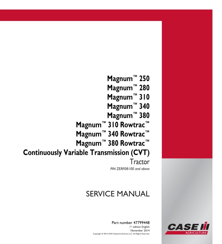
SERVICE MANUAL Magnum 250 Magnum 280 Magnum 310 Magnum 340 Magnum 380 Magnum 250 / Magnum 280 Magnum 310 / Magnum 340 Magnum 380 Magnum 310Rowtrac Magnum 340Rowtrac Magnum 380Rowtrac Continuously Variable Transmission (CVT) Tractor PIN ZERF08100 and above Magnum 310Rowtrac Magnum 340Rowtrac Magnum 380Rowtrac Continuously Variable Transmission (CVT) Tractor PIN ZERF08100 and above SERVICE MANUAL 1/4 Part number 47799448 Part number 47799448 1st edition English November 2014 Copyright 2014 CNH Industrial America LLC. All Rights Reserved.
Link Product / Engine Product Market Product Middle East Africa Engine Magnum 250 696110725 CVT TIER 2 [ZERF08100 - ] Magnum 250 696110725 CVT TIER 2 [ZERF08100 - ] Magnum 250 696110725 CVT TIER 2 [ZERF08100 - ] Magnum 250 696110725 CVT TIER 2 [ZERF08100 - ] Magnum 280 696110735 CVT TIER 2 [ZERF08100 - ] Magnum 280 696110735 CVT TIER 2 [ZERF08100 - ] Magnum 280 696110735 CVT TIER 2 [ZERF08100 - ] Magnum 280 696110735 CVT TIER 2 [ZERF08100 - ] Magnum 310 696110745 CVT TIER 2 [ZERF08100 - ] Magnum 310 696110745 CVT TIER 2 [ZERF08100 - ] Magnum 310 696110745 CVT TIER 2 [ZERF08100 - ] Magnum 310 696110745 CVT TIER 2 [ZERF08100 - ] Magnum 340 696110755 CVT TIER 2 [ZERF08100 - ] Magnum 340 696110755 CVT TIER 2 [ZERF08100 - ] Magnum 340 696110755 CVT TIER 2 [ZERF08100 - ] Magnum 340 696110755 CVT TIER 2 [ZERF08100 - ] Magnum 380 696110765 CVT TIER 2 [ZERF08100 - ] Magnum 380 696110765 CVT TIER 2 [ZERF08100 - ] Magnum 380 696110765 CVT TIER 2 [ZERF08100 - ] Magnum 380 696110765 CVT TIER 2 [ZERF08100 - ] Magnum 310 Rowtrac 696110775 CVT TIER 2 [ZERF08100 - ] Magnum 310 Rowtrac 696110775 CVT TIER 2 [ZERF08100 - ] Magnum 310 Rowtrac 696110775 CVT TIER 2 [ZERF08100 - ] F2CFA613G*E024 Asia Pacific F2CFA613G*E024 Australia New Zealand F2CFA613G*E024 Latin America F2CFA613G*E024 Latin America F2CFA613D*E024 Middle East Africa F2CFA613D*E024 Australia New Zealand F2CFA613D*E024 Asia Pacific F2CFA613D*E024 Australia New Zealand F2CFA613B*E024 Asia Pacific F2CFA613B*E024 Latin America F2CFA613B*E024 Middle East Africa F2CFA613B*E024 Australia New Zealand F2CFA614D*E022 Latin America F2CFA614D*E022 Asia Pacific F2CFA614D*E022 Middle East Africa F2CFA614D*E022 Asia Pacific F2CFA614A*E022 Latin America F2CFA614A*E022 Middle East Africa F2CFA614A*E022 Australia New Zealand F2CFA614A*E022 Asia Pacific F2CFA613B*E024 Latin America F2CFA613B*E024 Middle East Africa F2CFA613B*E024 47799448 06/11/2014
Product Market Product Australia New Zealand Engine Magnum 310 Rowtrac 696110775 CVT TIER 2 [ZERF08100 - ] Magnum 340 Rowtrac 696110785 CVT TIER 2 [ZERF08100 - ] Magnum 340 Rowtrac 696110785 CVT TIER 2 [ZERF08100 - ] Magnum 340 Rowtrac 696110785 CVT TIER 2 [ZERF08100 - ] Magnum 340 Rowtrac 696110785 CVT TIER 2 [ZERF08100 - ] Magnum 380 Rowtrac 696110795 CVT TIER 2 [ZERF08100 - ] Magnum 380 Rowtrac 696110795 CVT TIER 2 [ZERF08100 - ] Magnum 380 Rowtrac 696110795 CVT TIER 2 [ZERF08100 - ] Magnum 380 Rowtrac 696110795 CVT TIER 2 [ZERF08100 - ] F2CFA613B*E024 Asia Pacific F2CFA614D*E022 Latin America F2CFA614D*E022 Middle East Africa F2CFA614D*E022 Australia New Zealand F2CFA614D*E022 Asia Pacific F2CFA614A*E022 Middle East Africa F2CFA614A*E022 Australia New Zealand F2CFA614A*E022 Latin America F2CFA614A*E022 47799448 06/11/2014
https://www.ebooklibonline.com Hello dear friend! Thank you very much for reading. Enter the link into your browser. The full manual is available for immediate download. https://www.ebooklibonline.com
Contents INTRODUCTION Engine....................................................................................... 10 [10.001] Engine and crankcase ............................................................. 10.1 [10.101] Cylinder heads ..................................................................... 10.2 [10.202] Air cleaners and lines .............................................................. 10.3 [10.216] Fuel tanks .......................................................................... 10.4 [10.218] Fuel injection system............................................................... 10.5 [10.254] Intake and exhaust manifolds and muffler ......................................... 10.6 [10.304] Engine lubrication system.......................................................... 10.7 [10.310] Aftercooler.......................................................................... 10.8 [10.400] Engine cooling system ............................................................. 10.9 [10.414] Fan and drive .................................................................... 10.10 Power coupling........................................................................... 19 [19.100] Drive shaft.......................................................................... 19.1 [19.110] Flywheel damper ................................................................... 19.2 [19.120] Drive shaft shield assembly........................................................ 19.3 Transmission.............................................................................. 21 [21.504] Continuously Variable Transmission (CVT) ........................................ 21.1 [21.505] Continuously Variable Transmission (CVT) external controls...................... 21.2 [21.506] Continuously Variable Transmission (CVT) lubrication system .................... 21.3 [21.507] Continuously Variable Transmission (CVT) internal components.................. 21.4 [21.900] Hydraulic pump drive............................................................... 21.5 Four-Wheel Drive (4WD) system .................................................. 23 [23.202] Electro-hydraulic control ........................................................... 23.1 [23.314] Drive shaft.......................................................................... 23.2 Front axle system ....................................................................... 25 47799448 06/11/2014
[25.100] Powered front axle ................................................................. 25.1 [25.102] Front bevel gear set and differential ............................................... 25.2 [25.108] Final drive hub, steering knuckles, and shafts ..................................... 25.3 [25.122] Axle suspension control............................................................ 25.4 Rear axle system........................................................................ 27 [27.100] Powered rear axle.................................................................. 27.1 [27.106] Rear bevel gear set and differential................................................ 27.2 [27.610] Rear axle track yoke assembly .................................................... 27.3 Power Take-Off (PTO)................................................................. 31 [31.104] Rear electro-hydraulic control...................................................... 31.1 [31.110] One-speed rear Power Take-Off (PTO) ............................................ 31.2 [31.114] Two-speed rear Power Take-Off (PTO) ............................................ 31.3 [31.146] Front Power Take-Off (PTO) ....................................................... 31.4 Brakes and controls .................................................................... 33 [33.110] Parking brake or parking lock ...................................................... 33.1 [33.202] Hydraulic service brakes ........................................................... 33.2 [33.220] Trailer brake hydraulic control...................................................... 33.3 [33.224] Trailer brake pneumatic control .................................................... 33.4 [33.240] Emergency brake .................................................................. 33.5 Hydraulic systems....................................................................... 35 [35.000] Hydraulic systems.................................................................. 35.1 [35.102] Pump control valves................................................................ 35.2 [35.106] Variable displacement pump ....................................................... 35.3 [35.114] Three-point hitch control valve ..................................................... 35.4 [35.124] Three-point hitch hydraulic adjustment ............................................ 35.5 [35.204] Remote control valves ............................................................. 35.6 [35.300] Reservoir, cooler, and filters........................................................ 35.7 [35.304] Combination pump units ........................................................... 35.8 47799448 06/11/2014
Hitches, drawbars, and implement couplings.................................. 37 [37.110] Rear three-point hitch .............................................................. 37.1 [37.162] Front hitch.......................................................................... 37.2 Steering..................................................................................... 41 [41.101] Steering control .................................................................... 41.1 [41.200] Hydraulic control components...................................................... 41.2 [41.206] Pump............................................................................... 41.3 [41.432] Autoguidance steering ............................................................. 41.4 [41.910] Auxiliary steering................................................................... 41.5 Wheels...................................................................................... 44 [44.520] Rear wheels........................................................................ 44.1 Tracks and track suspension........................................................ 48 [48.100] Tracks .............................................................................. 48.1 [48.130] Track frame and driving wheels.................................................... 48.2 [48.134] Track tension units ................................................................. 48.3 [48.138] Track rollers ........................................................................ 48.4 Cab climate control..................................................................... 50 [50.100] Heating............................................................................. 50.1 [50.200] Air conditioning..................................................................... 50.2 [50.300] Cab pressurizing system........................................................... 50.3 Electrical systems....................................................................... 55 [55.010] Fuel injection system............................................................... 55.1 [55.012] Engine cooling system ............................................................. 55.2 [55.014] Engine intake and exhaust system................................................. 55.3 [55.024] Transmission control system....................................................... 55.4 [55.045] Front axle control system .......................................................... 55.5 [55.046] Rear axle control system........................................................... 55.6 [55.050] Heating, Ventilation, and Air-Conditioning (HVAC) control system................. 55.7 47799448 06/11/2014
[55.051] Cab Heating, Ventilation, and Air-Conditioning (HVAC) controls................... 55.8 [55.100] Harnesses and connectors......................................................... 55.9 [55.130] Rear three-point hitch electronic control system ................................. 55.10 [55.201] Engine starting system........................................................... 55.11 [55.301] Alternator......................................................................... 55.12 [55.302] Battery............................................................................ 55.13 [55.510] Cab or platform harnesses and connectors...................................... 55.14 [55.512] Cab controls...................................................................... 55.15 [55.513] Cab transmission controls........................................................ 55.16 [55.518] Wiper and washer system........................................................ 55.17 [55.640] Electronic modules............................................................... 55.18 [55.988] Selective Catalytic Reduction (SCR) electrical system .......................... 55.19 [55.DTC] FAULT CODES.................................................................. 55.20 Platform, cab, bodywork, and decals............................................. 90 [90.100] Engine hood and panels ........................................................... 90.1 [90.102] Engine shields, hood latches, and trims ........................................... 90.2 [90.124] Pneumatically-adjusted operator seat.............................................. 90.3 [90.150] Cab................................................................................. 90.4 [90.151] Cab interior......................................................................... 90.5 [90.160] Cab interior trim and panels........................................................ 90.6 47799448 06/11/2014
INTRODUCTION 47799448 06/11/2014 1
INTRODUCTION Foreword - Important notice regarding equipment servicing All repair and maintenance work listed in this manual must be carried out only by qualified dealership personnel, strictly complying with the instructions given, and using, whenever possible, the special tools. Anyone who performs repair and maintenance operations without complying with the procedures provided herein shall be responsible for any subsequent damages. The manufacturer and all the organizations of its distribution chain, including - without limitation - national, regional, or local dealers, reject any responsibility for damages caused by parts and/or components not approved by the manu- facturer, including those used for the servicing or repair of the product manufactured or marketed by the manufacturer. In any case, no warranty is given or attributed on the product manufactured or marketed by the manufacturer in case of damages caused by parts and/or components not approved by the manufacturer. The information in this manual is up-to-date at the date of the publication. It is the policy of the manufacturer for continuous improvement. Some information could not be updated due to modifications of a technical or commercial type, or changes to the laws and regulations of different countries. In case of questions, refer to your CASE IH Sales and Service Networks. 47799448 06/11/2014 3
INTRODUCTION Safety rules Personal safety This is the safety alert symbol. It is used to alert you to potential personal injury hazards. Obey all safety messages that follow this symbol to avoid possible death or injury. Throughout this manual you will find the signal words DANGER, WARNING, and CAUTION followed by special in- structions. These precautions are intended for the personal safety of you and those working with you. Read and understand all the safety messages in this manual before you operate or service the machine. DANGER indicates a hazardous situation that, if not avoided, will result in death or serious injury. WARNING indicates a hazardous situation that, if not avoided, could result in death or serious injury. CAUTION indicates a hazardous situation that, if not avoided, could result in minor or moderate injury. FAILURE TO FOLLOW DANGER, WARNING, AND CAUTION MESSAGES COULD RESULT IN DEATH OR SERIOUS INJURY. Machine safety NOTICE: Notice indicates a situation that, if not avoided, could result in machine or property damage. Throughout this manual you will find the signal word Notice followed by special instructions to prevent machine or property damage. The word Notice is used to address practices not related to personal safety. Information NOTE: Note indicates additional information that clarifies steps, procedures, or other information in this manual. Throughout this manual you will find the word Note followed by additional information about a step, procedure, or other information in the manual. The word Note is not intended to address personal safety or property damage. 47799448 06/11/2014 4
INTRODUCTION Safety rules - General maintenance safety General maintenance safety Keep the area used for servicing the machine clean and dry. Clean up spilled fluids. Service the machine on a firm, level surface. Install guards and shields after you service the machine. Close all access doors and install all panels after servicing the machine. Do not attempt to clean, lubricate, clear obstructions, or make adjustments to the machine while it is in motion or while the engine is running. Always make sure that working area is clear of tools, parts, other persons and pets before you start operating the machine. Unsupported hydraulic cylinders can lose pressure and drop the equipment, causing a crushing hazard. Do not leave equipment in a raised position while parked or during service, unless the equipment is securely supported. Jack or lift the machine only at jack or lift points indicated in this manual. Incorrect towing procedures can cause accidents. When you tow a disabled machine follow the procedure in this manual. Use only rigid tow bars. Stop the engine, remove the key, and relieve pressure before you connect or disconnect fluid lines. Stop the engine and remove the key before you connect or disconnect electrical connections. Scalding can result from incorrect removal of coolant caps. Cooling systems operate under pressure. Hot coolant can spray out if you remove a cap while the system is hot. Allow the system to cool before you remove the cap. When you remove the cap, turn it slowly to allow pressure to escape before you completely remove the cap. Replace damaged or worn tubes, hoses, electrical wiring, etc. The engine, transmission, exhaust components, and hydraulic lines may become hot during operation. Take care when you service such components. Allow surfaces to cool before you handle or disconnect hot components. Wear protective equipment when appropriate. When welding, follow the instructions in the manual. Always disconnect the battery before you weld on the machine. Always wash your hands after you handle battery components. 47799448 06/11/2014 5
SERVICE MANUAL Engine Magnum 250 696110725 CVT TIER 2 [ZERF08100 - ] , Magnum 280 696110735 CVT TIER 2 [ZERF08100 - ] , Magnum 310 696110745 CVT TIER 2 [ZERF08100 - ] , Magnum 310 Rowtrac 696110775 CVT TIER 2 [ZERF08100 - ] , Magnum 340 696110755 CVT TIER 2 [ZERF08100 - ] , Magnum 340 Rowtrac 696110785 CVT TIER 2 [ZERF08100 - ] , Magnum 380 696110765 CVT TIER 2 [ZERF08100 - ] , Magnum 380 Rowtrac 696110795 CVT TIER 2 [ZERF08100 - ] 47799448 06/11/2014 10
Engine - Engine and crankcase Engine - Remove Prior operation: Disconnect the batteries Battery - Disconnect (55.302) Prior operation: Remove the hood Hood - Remove (90.100) Prior operation: Side shield - Remove (90.102) Prior operation: Recover the refrigerant Air conditioning - Recover (50.200) Prior operation: Drain the coolant Engine cooling system - Emptying (10.400) Prior operation: Engine cooling system - Remove (10.400) NOTE: Clean all fittings before disconnecting. NOTE: Cap or plug all lines and ports when disconnecting hydraulic components. 1. Disconnect the harness connector to the humidity sen- sor (1) and the air restriction sensor (2). Disengage the hose clamp (3) and disconnect the hose from the air in- take tube. 1 RAIL13TR04202AA 2. Disconnect the clamps (1) from each end of the air intake tube and remove the tube. 2 RAIL13TR04211AA 3. Disconnect the high pressure air conditioning hose (1) and the coolant lines (2). Plug or cap all ports and lines. 3 RAIL13TR04230AA 47799448 06/11/2014 10.1 [10.001] / 3
Engine - Engine and crankcase 4. Disconnect the power cable (1), the ground cable (2) and the ignition wire (3) from the starter. 4 RAIL14TR01944AA 5. Disconnect the suspended axle harness connectors (1) if equipped. 5 RAIL13TR04237AA 6. Remove the two bolts (1) from the rear engine mount cover plate on both sides, (left hand side shown). 6 RAIL14TR01944AA 7. Remove the engine mount cover plate (left hand side). 7 RAIL14TR01945AA 47799448 06/11/2014 10.1 [10.001] / 4
Engine - Engine and crankcase 8. Remove the two tube clamps (1) securing the hydraulic cooler tubes. 8 RAIL13TR04232AA 9. At the front of the engine, remove the tube clamp (1) for the oil cooler tube. 9 RAIL14TR01915AA 10. Using special tool 380000795 (1), disconnect the hy- draulic tubes and set them aside. 10 RAIL14TR01924AA 11. At the rear of the engine, remove the oil cooler tube clamp (1). 11 RAIL13TR04236AA 47799448 06/11/2014 10.1 [10.001] / 5
Engine - Engine and crankcase 12. Disconnect the low pressure air conditioning line (1). Plug or cap the fittings. 12 RAIL13TR04228AA 13. Disengage the hose clamp and disconnect the engine controller oil line (1). 13 RAIL13TR04227AA 14. Removethethreemountingbolts(1)securingthefuse panel bracket. NOTE: Cut and remove any wire ties securing the harness. 14 RAIL13TR04216AA 15. Remove the fuse panel and set to the side. 15 RAIL13TR04214AA 47799448 06/11/2014 10.1 [10.001] / 6
Engine - Engine and crankcase 16. Disconnect the harness connector (1) for the engine grid heater and the power supply cable (2). 16 RAIL13TR04219AA 17. Disconnect the vent hose (1) from the intake manifold. 17 RAIL13TR04218AA 18. Disconnecttheharnessconnector(1)forthefandrive. 18 RAIL13TR04220AA 19. Remove the air conditioning compressor mounting bolt (1), and disconnect the ground wire (2). 19 RAIL13TR04224AA 47799448 06/11/2014 10.1 [10.001] / 7
Engine - Engine and crankcase 20. Disconnect the harness connector to the high pres- sure switch (1). 20 RAIL13TR04223AA 21. Disconnect the alternator excite wire connector (1) and the CAN bus connector (2). 21 RAIL13TR04221AA 22. Remove the nut and disconnect the alternator output cable (1). 22 RAIL13TR04231AA 23. Disconnect the harness connector (1) to the engine controller. 23 RAIL13TR04226AA 47799448 06/11/2014 10.1 [10.001] / 8
Engine - Engine and crankcase 24. Remove the bolts (1) and the drive shaft cover. Set the cover aside. 24 RCPH10CCH813AAB 25. Mark the alignment of the drive shaft (1). Remove the four bolts and remove the drive shaft from the fly- wheel. 25 RCPH10CCH817AAB 26. Remove the bolts (1) from the plate (2) for the right hand rear engine mount. 26 RCPH10CCH925AAB 27. Under the front frame, remove the front engine mount nut. 27 RAIL13TR04246AA 47799448 06/11/2014 10.1 [10.001] / 9
Engine - Engine and crankcase WARNING Heavy objects! Lift and handle all heavy components us- ing lifting equipment with adequate capacity. Always support units or parts with suitable slings or hooks. Make sure the work area is clear of all bystanders. Failure to comply could result in death or seri- ous injury. 28. W0398A Use an appropriate device to support the engine, and carefully remove the engine making sure all hoses, lines and harnesses are disconnected. 28 RAIL14TR01947AA 29. Remove the right hand rear engine mount. Inspect for wear and/or damage. Replace as required. Repeat for the left side. 29 RCPH07CCH166AAB 30. Remove the four bolts (1) securing the brackets (2) for the front engine mount. 31. Remove the bolt (3) securing the front engine mount (4). 32. Inspect the mount for wear and/or damage. Replace as required. 30 RCPH10CCH833AAB Next operation: Engine - Install (10.001) 47799448 06/11/2014 10.1 [10.001] / 10
Suggest: If the above button click is invalid. Please download this document first, and then click the above link to download the complete manual. Thank you so much for reading
Engine - Engine and crankcase Engine - Install Prior operation: Engine - Remove (10.001) 1. If removed, install the front engine mounting brackets (1). 2. Torque the four mounting bolts (2) to 101 - 113 N m (75 - 83 lb ft). 3. Torque the ISO mount support bolt nut (3) to 160 - 220 N m (118 - 162 lb ft). 1 RCPH10CCH833AAB 4. Install the right hand (shown) and left hand rear engine ISO mounts. 2 RCPH07CCH166AAB WARNING Heavy objects! Lift and handle all heavy components using lift- ing equipment with adequate capacity. Always support units or parts with suitable slings or hooks. Make sure the work area is clear of all bystanders. Failure to comply could result in death or seri- ous injury. 5. W0398A Properly support the engine. Raise and move the en- gine into the front support frame. 3 RAIL14TR01947AA 6. Install the front engine mounting nut. 4 RAIL13TR04246AA 47799448 06/11/2014 10.1 [10.001] / 11
https://www.ebooklibonline.com Hello dear friend! Thank you very much for reading. Enter the link into your browser. The full manual is available for immediate download. https://www.ebooklibonline.com


