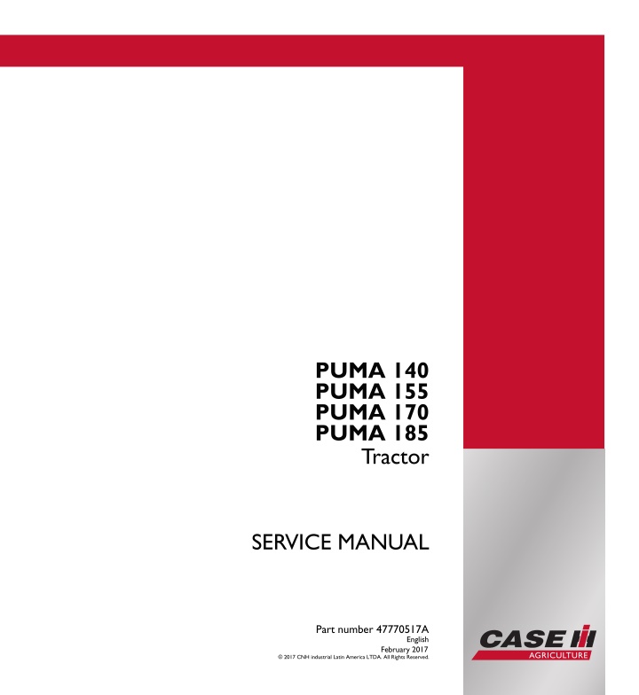
CASE IH PUMA 155 Tractor Service Repair Manual Instant Download 6
CASE IH PUMA 155 Tractor Service Repair Manual Instant Download 6
Download Presentation

Please find below an Image/Link to download the presentation.
The content on the website is provided AS IS for your information and personal use only. It may not be sold, licensed, or shared on other websites without obtaining consent from the author. If you encounter any issues during the download, it is possible that the publisher has removed the file from their server.
You are allowed to download the files provided on this website for personal or commercial use, subject to the condition that they are used lawfully. All files are the property of their respective owners.
The content on the website is provided AS IS for your information and personal use only. It may not be sold, licensed, or shared on other websites without obtaining consent from the author.
E N D
Presentation Transcript
SERVICE MANUAL PUMA 140 PUMA 155 PUMA 170 PUMA 185 Tractor PUMA 140 PUMA 155 PUMA 170 PUMA 185 Tractor Part number 47770517 1/1 SERVICE MANUAL Part number 47770517A English February 2017 2017 CNH industrial Latin America LTDA. All Rights Reserved.
SERVICE MANUAL PUMA 140 With cab, 18X6, TIER 3 [HCCZ185CECW21177 - ] PUMA 155 With cab, 18X6, TIER 3 [HCCZ185CECW21177 - ] PUMA 170 With cab, 18X6, TIER 3 [HCCZ185CECW21177 - ] PUMA 185 With cab, 18X6, TIER 3 [HCCZ185CECW21177 - ] 47770517A 15/02/2017 EN
Link Product / Engine Product Market Product Latin America Engine PUMA 140 Com cabine, 18x6, TIER 3 [HCCZ185CECW21177 - ] PUMA 155 Com cabine, 18x6, TIER 3 [HCCZ185CECW21177 - ] PUMA 170 Com cabine, 18x6, TIER 3 [HCCZ185CECW21177 - ] PUMA 185 Com cabine, 18x6, TIER 3 [HCCZ185CECW21177 - ] F4DE9684J*J106 Latin America F4DE9684V*J101 Latin America F4DE9687V*J105 Latin America F4DE9684T*J102 47770517A 15/02/2017
https://www.ebooklibonline.com Hello dear friend! Thank you very much for reading. Enter the link into your browser. The full manual is available for immediate download. https://www.ebooklibonline.com
Contents INTRODUCTION Engine....................................................................................... 10 [10.001] Engine and crankcase ............................................................. 10.1 [10.103] Crankshaft and flywheel............................................................ 10.2 [10.216] Fuel tanks .......................................................................... 10.3 [10.250] Turbocharger and lines............................................................. 10.4 [10.254] Intake and exhaust manifolds and muffler ......................................... 10.5 [10.400] Engine cooling system ............................................................. 10.6 Clutch ....................................................................................... 18 [18.110] Clutch and components ............................................................ 18.1 Transmission.............................................................................. 21 [21.111] Semi-Powershift transmission...................................................... 21.1 [21.133] Semi-Powershift transmission external controls ................................... 21.2 [21.152] Semi-Powershift transmission internal components ............................... 21.3 [21.160] Creeper ............................................................................ 21.4 Four-Wheel Drive (4WD) system .................................................. 23 [23.202] Electro-hydraulic control ........................................................... 23.1 Front axle system ....................................................................... 25 [25.100] Powered front axle ................................................................. 25.1 [25.102] Front bevel gear set and differential ............................................... 25.2 [25.108] Final drive hub, steering knuckles, and shafts ..................................... 25.3 Rear axle system........................................................................ 27 [27.100] Powered rear axle.................................................................. 27.1 [27.106] Rear bevel gear set and differential................................................ 27.2 [27.120] Planetary and final drives .......................................................... 27.3 Power Take-Off (PTO)................................................................. 31 47770517A 15/02/2017
[31.104] Rear electro-hydraulic control...................................................... 31.1 [31.114] Two-speed rear Power Take-Off (PTO) ............................................ 31.2 Brakes and controls .................................................................... 33 [33.202] Hydraulic service brakes ........................................................... 33.1 [33.300] Pneumatic service brakes.......................................................... 33.2 [33.110] Parking brake or parking lock ...................................................... 33.3 Hydraulic systems....................................................................... 35 [35.000] Hydraulic systems.................................................................. 35.1 [35.300] Reservoir, cooler, and filters........................................................ 35.2 [35.106] Variable displacement pump ....................................................... 35.3 [35.102] Pump control valves................................................................ 35.4 [35.105] Charge pump....................................................................... 35.5 [35.204] Remote control valves ............................................................. 35.6 [35.114] Three-point hitch control valve ..................................................... 35.7 [35.116] Three-point hitch cylinder .......................................................... 35.8 Pneumatic system ...................................................................... 36 [36.100] Pneumatic system.................................................................. 36.1 Hitches, drawbars, and implement couplings.................................. 37 [37.100] Drawbars and towing hitches ...................................................... 37.1 [37.110] Rear three-point hitch .............................................................. 37.2 Frames and ballasting................................................................. 39 [39.100] Frame .............................................................................. 39.1 [39.140] Ballasts and supports .............................................................. 39.2 Steering..................................................................................... 41 [41.101] Steering control .................................................................... 41.1 [41.106] Tie rods............................................................................. 41.2 [41.200] Hydraulic control components...................................................... 41.3 47770517A 15/02/2017
[41.206] Pump............................................................................... 41.4 [41.216] Cylinders ........................................................................... 41.5 Wheels...................................................................................... 44 [44.511] Front wheels........................................................................ 44.1 [44.520] Rear wheels........................................................................ 44.2 Cab climate control..................................................................... 50 [50.100] Heating............................................................................. 50.1 [50.104] Ventilation .......................................................................... 50.2 [50.200] Air conditioning..................................................................... 50.3 Electrical systems....................................................................... 55 [55.100] Harnesses and connectors......................................................... 55.1 [55.302] Battery.............................................................................. 55.2 [55.640] Electronic modules................................................................. 55.3 [55.045] Front axle control system .......................................................... 55.4 [55.130] Rear three-point hitch electronic control system ................................... 55.5 [55.DTC] FAULT CODES.................................................................... 55.6 Platform, cab, bodywork, and decals............................................. 90 [90.150] Cab................................................................................. 90.1 [90.151] Cab interior......................................................................... 90.2 [90.100] Engine hood and panels ........................................................... 90.3 [90.102] Engine shields, hood latches, and trims ........................................... 90.4 47770517A 15/02/2017
INTRODUCTION 47770517A 15/02/2017 1
INTRODUCTION Safety rules - Ecology and the environment Soil, air, and water quality is important for all industries and life in general. When legislation does not yet rule the treatment of some of the substances that advanced technology requires, sound judgment should govern the use and disposal of products of a chemical and petrochemical nature. Familiarize yourself with the relative legislation applicable to your country, and make sure that you understand this legislation. Where no legislation exists, obtain information from suppliers of oils, filters, batteries, fuels, anti-freeze, cleaning agents, etc., with regard to the effect of these substances on man and nature and how to safely store, use, and dispose of these substances. Helpful hints Avoid the use of cans or other inappropriate pressurized fuel delivery systems to fill tanks. Such delivery systems may cause considerable spillage. In general, avoid skin contact with all fuels, oils, acids, solvents, etc. Most of these products contain substances that may be harmful to your health. Modern oils contain additives. Do not burn contaminated fuels and or waste oils in ordinary heating systems. Avoid spillage when you drain fluids such as used engine coolant mixtures, engine oil, hydraulic fluid, brake fluid, etc. Do not mix drained brake fluids or fuels with lubricants. Store all drained fluids safely until you can dispose of the fluids in a proper way that complies with all local legislation and available resources. Do not allow coolant mixtures to get into the soil. Collect and dispose of coolant mixtures properly. The air-conditioning system contains gases that should not be released into the atmosphere. Consult an air-condi- tioning specialist or use a special extractor to recharge the system properly. Repair any leaks or defects in the engine cooling system or hydraulic system immediately. Do not increase the pressure in a pressurized circuit as this may lead to a component failure. Protect hoses during welding. Penetrating weld splatter may burn a hole or weaken hoses, allowing the loss of oils, coolant, etc. Battery recycling Batteries and electric accumulators contain several substances that can have a harmful effect on the environment if the batteries are not properly recycled after use. Improper disposal of batteries can contaminate the soil, groundwater, and waterways. CASE IH strongly recommends that you return all used batteries to a CASE IH dealer, who will dispose of the used batteries or recycle the used batteries properly. In some countries, this is a legal requirement. Mandatory battery recycling NOTE: The following requirements are mandatory in Brazil. Batteries are made of lead plates and a sulfuric acid solution. Because batteries contain heavy metals such as lead, CONAMA Resolution 401/2008 requires you to return all used batteries to the battery dealer when you replace any batteries. Do not dispose of batteries in your household garbage. Points of sale are obliged to: Accept the return of your used batteries Store the returned batteries in a suitable location Send the returned batteries to the battery manufacturer for recycling 47770517A 15/02/2017 9
INTRODUCTION Safety rules Personal safety This is the safety alert symbol. It is used to alert you to potential personal injury hazards. Obey all safety messages that follow this symbol to avoid possible death or injury. Throughout this manual and on machine safety signs, you will find the signal words DANGER, WARNING, and CAU- TION followed by special instructions. These precautions are intended for the personal safety of you and those working with you. Read and understand all the safety messages in this manual before you operate or service the machine. DANGER indicates a hazardous situation that, if not avoided, will result in death or serious injury. The color associated with DANGER is RED. WARNING indicates a hazardous situation that, if not avoided, could result in death or serious injury. The color associated with WARNING is ORANGE. CAUTION indicates a hazardous situation that, if not avoided, could result in minor or moderate injury. The color associated with CAUTION is YELLOW. FAILURE TO FOLLOW DANGER, WARNING, AND CAUTION MESSAGES COULD RESULT IN DEATH OR SERIOUS INJURY. Machine safety NOTICE: Notice indicates a situation that, if not avoided, could result in machine damage or property damage. The color associated with Notice is BLUE. Throughout this manual you will find the signal word Notice followed by special instructions to prevent machine dam- age or property damage. The word Notice is used to address practices not related to personal safety. Information NOTE: Note indicates additional information that clarifies steps, procedures, or other information in this manual. Throughout this manual you will find the word Note followed by additional information about a step, procedure, or other information in the manual. The word Note is not intended to address personal safety or property damage. 47770517A 15/02/2017 10
INTRODUCTION Basic instructions - Shop and assembly Shimming For each adjustment operation, select adjusting shims and measure the adjusting shims individually using a microm- eter, then add up the recorded values. Do not rely on measuring the entire shimming set, which may be incorrect, or the rated value shown on each shim. Rotating shaft seals For correct rotating shaft seal installation, proceed as follows: 1. Before assembly, allow the seal to soak in the oil it will be sealing for at least thirty minutes. 2. Thoroughly clean the shaft and check that the working surface on the shaft is not damaged. 3. Position the sealing lip facing the fluid. NOTE: With hydrodynamic lips, take into consideration the shaft rotation direction and position the grooves so that they will move the fluid towards the inner side of the seal. 4. Coat the sealing lip with a thin layer of lubricant (use oil rather than grease). Fill the gap between the sealing lip and the dust lip on double lip seals with grease. 5. Insert the seal in its seat and press down using a flat punch or seal installation tool. Do not tap the seal with a hammer or mallet. 6. While you insert the seal, check that the seal is perpendicular to the seat. When the seal settles, make sure that the seal makes contact with the thrust element, if required. 7. To prevent damage to the seal lip on the shaft, position a protective guard during installation operations. O-ring seals Lubricate the O-ring seals before you insert them in the seats. This will prevent the O-ring seals from overturning and twisting, which would jeopardize sealing efficiency. Sealing compounds Apply a sealing compound on the mating surfaces when specified by the procedure. Before you apply the sealing compound, prepare the surfaces as directed by the product container. Spare parts Only use CNH Original Parts or CASE IH Original Parts. Only genuine spare parts guarantee the same quality, duration, and safety as original parts, as they are the same parts that are assembled during standard production. Only CNH Original Parts or CASE IH Original Parts can offer this guarantee. When ordering spare parts, always provide the following information: Machine model (commercial name) and Product Identification Number (PIN) Part number of the ordered part, which can be found in the parts catalog 47770517A 15/02/2017 11
SERVICE MANUAL Engine PUMA 140 With cab, 18X6, TIER 3 [HCCZ185CECW21177 - ] PUMA 155 With cab, 18X6, TIER 3 [HCCZ185CECW21177 - ] PUMA 170 With cab, 18X6, TIER 3 [HCCZ185CECW21177 - ] PUMA 185 With cab, 18X6, TIER 3 [HCCZ185CECW21177 - ] 47770517A 15/02/2017 10
Engine - Engine and crankcase Engine - Connect CAUTION Heavy object! The component is heavy. Use care not to drop the component when installing, removing, or handling. Failure to comply could result in minor or moderate injury. C0095A 1. Line up the front support and engine assembly with the transmission. Install the engine on the transmission fixing bolts. Torque to 285 315 N m (2522 2788 lb in). Remove the separation kit from the tractor. 1 BTB0155A 2. Install the flywheel speed sensor. 2 BAIS06CCM087AVA 3. Install the spacer (2) and install the fixing bolts (1). 3 BAIS06CCM088AVA 47770517A 15/02/2017 10.1 [10.001] / 3
Engine - Engine and crankcase 4. Connect the supply hose of the hydraulic brake master cylinder. 4 BAIS06CCM085AVA 5. Connect the transmission oil cooler pipes (1) and (2). 5 BAIS06CCM032AVA 6. Install the transmission shaft flange, if installed. Tighten the M24 nut (if installed) to 294 N m(217 lb ft). Tighten the M12 bolt (if installed) to 80 N m (59 lb ft) . 6 BSD1917A 7. Install the drive shaft and then the metal guard. 8. Connect the differential lock supply hose (1). 7 BVE0282A 47770517A 15/02/2017 10.1 [10.001] / 4
Engine - Engine and crankcase 9. Connect the supply hose of the hydraulic brake valve. 8 BAIS06CCM086AVA 10. Connect the fuel supply and return lines. 9 BAIS06CCM137AVA 11. Connect the oil supply hoses of the steering cylinder (1) and (2). 10 BVE0218A 12. Connect the high-pressure hose (1) and the low-pres- sure hose (2) of the air conditioning. 11 BAIS06CCM001AVA 47770517A 15/02/2017 10.1 [10.001] / 5
Engine - Engine and crankcase 13. Connect the cab heater hose. 12 BAIS06CCM064AVA 14. Connect the cab heater hose to the radiator. 13 BAIS06CCM083AVA 15. Connect the positive battery cable (2) and the nega- tive cable (ground) (1). 16. Connect the engine wire harness connectors. 14 BVE0403A 17. Install the exhaust muffler. See Exhaust muffler - Install (10.254). 47770517A 15/02/2017 10.1 [10.001] / 6
Engine - Engine and crankcase 18. Wheninstalled, installtheradar(2). Connecttheradar electrical connector (1). 15 BAIS06CCM080AVB 19. Install the side shield on both sides of the engine. 20. Connect the battery ground lead. 21. Fill the engine cooling system. For more information see Engine coolant replace (10.400). Next operation: Front ballast - Install (39.140) 47770517A 15/02/2017 10.1 [10.001] / 7
Engine - Engine and crankcase Engine - Remove DANGER Heavy objects! Lift and handle all heavy components using lifting equipment with adequate capacity. Always support units or parts with suitable slings or hooks. Make sure the work area is clear of all bystanders. Failure to comply will result in death or serious injury. D0076A DANGER Pressurized system! Always remove all pressure before working on the hydraulic system. Follow the pressure BLEED program in the Configuration Mode to remove the pressure in the entire hydraulic system. Failure to comply will result in death or serious injury. D0035A Prior operation: Front frame - Remove (39.100) 1. Disconnect the lighting wiring electrical connector. 1 BAIS06CCM288AVA 2. Remove the hood. 3. Remove the exhaust muffler. See Exhaust muffler - Remove (10.254). 4. Disconnect the radar electrical connector (1). Remove the radar (2). 2 BAIS06CCM080AVB 47770517A 15/02/2017 10.1 [10.001] / 8
Engine - Engine and crankcase 5. Disconnect the cab heater coolant hose. 3 BAIS06CCM083AVA 6. Remove the electrical wiring from the air filter frame (1). Remove the filter-drier from the air filter frame (2). 4 BAIS06CCM129AVA 7. Disconnect the high-pressure hose (1) and the low- pressure hose (2) of the air conditioning. Remove the high pressure hose fixing bolt (3) and clamp (4). NOTE:Youdonotneedtodraintheairconditioningsystem because the joints are self-sealing. 5 BAIS06CCM130AVB 8. Disconnect the hydraulic brake hose. 6 BAIS06CCM086AVA 47770517A 15/02/2017 10.1 [10.001] / 9
Engine - Engine and crankcase 9. Disconnect the differential lock supply hose (1) and re- move the support (2). 7 BAIS06CCM037AVA 10. Disconnect the steering cylinder supply hoses (1) and (2). NOTE: Note the position of the steering cylinder oil feed hoses. 8 BVE0218A 11. Disconnect the hydraulic brake ventilation hose. 9 BAIS06CCM073AVA 12. Disconnect the engine wiring electrical connectors. 10 BVE0403A_37 47770517A 15/02/2017 10.1 [10.001] / 10
Engine - Engine and crankcase 13. Disconnect the fuel supply and return lines. 11 BAIS06CCM137AVA 14. Remove the attachment drive chain. 12 BAIS06CCM131AVA 15. Remove the air-conditioning compressor assembly, the condenser filter-drier, and the tubing from the en- gine. Do not disconnect the tubing. See Air-condi- tioning compressor - Remove (50.200). 16. Disconnect the expansion tube (1) and the engine breather tube (2). 13 BAIS06CCM133AVA 17. Disconnect the turbo air filter outlet hose. 14 BAIS06CCM163AVA 47770517A 15/02/2017 10.1 [10.001] / 11
Suggest: If the above button click is invalid. Please download this document first, and then click the above link to download the complete manual. Thank you so much for reading
Engine - Engine and crankcase 18. Remove the front fixing bolts of the air filter mounting frame. 15 BAIS06CCM135AVA 19. Remove the engine wiring clamp fixing bolts and repo- sition the engine wiring on top of the engine. 16 BVE0304A 20. Remove the rear fixing bolts of the air filter mounting frame. 17 BVE0305A 21. Remove the air filter mounting frame with a suitable chain and a hoist. 18 BVE0307A 47770517A 15/02/2017 10.1 [10.001] / 12
https://www.ebooklibonline.com Hello dear friend! Thank you very much for reading. Enter the link into your browser. The full manual is available for immediate download. https://www.ebooklibonline.com


