CASE IH STX450 Tractor Service Repair Manual Instant Download
CASE IH STX450 Tractor Service Repair Manual Instant Download

Download Presentation

Please find below an Image/Link to download the presentation.
The content on the website is provided AS IS for your information and personal use only. It may not be sold, licensed, or shared on other websites without obtaining consent from the author. If you encounter any issues during the download, it is possible that the publisher has removed the file from their server.
You are allowed to download the files provided on this website for personal or commercial use, subject to the condition that they are used lawfully. All files are the property of their respective owners.
The content on the website is provided AS IS for your information and personal use only. It may not be sold, licensed, or shared on other websites without obtaining consent from the author.
E N D
Presentation Transcript
https://www.ebooklibonline.com Hello dear friend! Thank you very much for reading. Enter the link into your browser. The full manual is available for immediate download. https://www.ebooklibonline.com
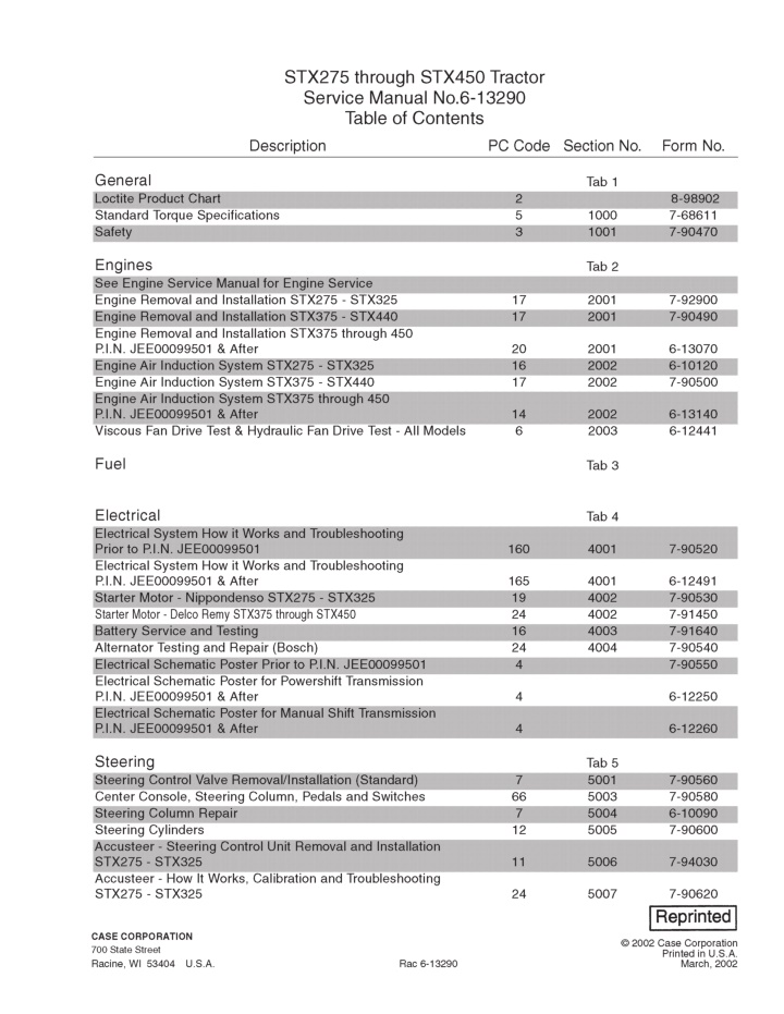
1001 Section 1001 SAFETY CASE CORPORATION 700 State Street Racine, WI 53404 U.S.A. CASE CANADA CORPORATION 3350 South Service Road Burlington, ON L7N 3M6 1999 Case Corporation Printed in U.S.A. February, 1999 Rac 7-90470 CANADA
Template Name: SM_2_col Template Date: 1997_01_13 Alt= to hide template information Alt+ to display template information 1001-2 SAFETY WARNING: THIS SAFETY ALERT SYMBOL INDICATES IMPORTANT SAFETY MESSAGES IN THIS MANUAL. WHEN YOU SEE THIS SYMBOL, CAREFULLY READ THE MESSAGE THAT FOLLOWS AND BE ALERT TO THE POSSIBILITY OF PERSONAL INJURY OR DEATH.** ! M171B To prevent injury always follow the Warning, Caution and Danger notes in this section and throughout the manual. WARNING: Before starting engine study Operators Manual safety messages. Read all safety signs on machine. Clear the area of other persons. Learn and practice safe use of controls before operating. It is your responsibility to understand and follow manufacturers instructions on machine operation, service, and to observe pertinent laws and regulations. Operator and Service Manuals may be obtained from your equipment dealer. Put the Do Not Operate tag shown below on the key for the key switch when keys are removed for servicing or repairing the machine. Tags are available from your service parts supplier. ! Before servicing a machine, park the machine on hard level ground. Turn off the engine, apply the parking brake and remove the key from the key switch. Put blocks in front of and behind either the front or rear wheels. M103A WARNING: If you wear clothing that is too loose or do not use the correct safety equipment for your job, you can be injured. Always wear clothing that will not catch on objects. Extra safety equipment that can be required includes hard hat, safety shoes, ear protection, eye or face protection, heavy gloves and reflector clothing. ! M492 WARNING: When working in the area of the fan belt with the engine running, avoid loose clothingifpossible,anduseextremecaution. ! M493 WARNING: When doing checks and tests on the equipment hydraulics, follow the procedures as they are written. DO NOT change the procedure. ! MS99B001 M494 WARNING: Read the operators manual to familiarize yourself with the correct control functions. ! WARNING: When putting the hydraulic cylinders on this machine through the necessary cycles to check operation or to remove air from a circuit, make sure all people are out of the way. M489 ! WARNING: Operate the machine and equipment controls from the seat position only. Any other method could result in serious injury. M495 ! M490 WARNING: Always wear heat protective gloves to prevent burning your hands when handling heated parts. ! WARNING: This is one man machine, no riders allowed. SM121A ! M491 Rac 7-90470 Issued 2-99 Printed in U.S.A.
Template Name: SM_2_col Template Date: 1997_01_13 Alt= to hide template information Alt+ to display template information 1001-3 WARNING: Lower all attachments to the ground or use stands to safely support the attachments before you do any maintenance or service. WARNING: Engine exhaust fumes can cause death. If it is necessary to start the engine in a closed place, remove the exhaust fumes from the area with an exhaust pipe extension. Open the door and get outside air into the area. ! ! M496 M502 WARNING: Hydraulic oil or diesel fuel leaking under pressure can penetrate the skin and cause infection or other injury. To Prevent Personal Injury: Relieve all pressure, before disconnecting fluid lines. Before applying pressure, make sure all connections are tight and components are in good condition. Never use your hand to check for suspected leaks under pressure. Use a piece of cardboard or wood for this purpose. If injured by leaking fluid, see your doctor immediately. WARNING: When the battery electrolyte is frozen, the battery can explode if (1), you try to charge the battery, or (2), you try to jump start and run the engine. To prevent the battery electrolyte from freezing, try to keep the battery at full charge. If you do not follow these instructions, you or others in the area can be injured. ! ! M503 WARNING: Batteries contain acid and explosive gas. Explosions can result from sparks, flames or wrong cable connections. To connect the jumper cables correctly to the battery of this machine see the Operators Manual. Failure to follow these instructions can cause serious injury or death. SM171A ! WARNING: When removing hardened pins such as a pivot pin, or a hardened shaft, use a soft head (brass or bronze) hammer or use a driver made from brass or bronze and a steel head hammer. ! M504 M497 ROLL OVER PROTECTIVE STRUCTURE (ROPS) ROPS, the operators seat, the seat belts and all mounting, accessories and wiring inside the operators protective system must be carefully checked after a tractor accident and all parts with damage must be replaced immediately. DO NOT TRY TO MAKE REPAIRS OR WELD THE ROPS. WARNING: When using a hammer to remove and install pivot pins or separate parts using compressed air or using a grinder, wear eye protection that completely encloses the eyes (approved goggles or other approved eye protectors). ! M498 WARNING: Use suitable floor (service) jacks or chain hoist to raise wheels or tracks off the floor. Always block machine in place with suitable safety stands ! Safety Rules: 1. Do not make modifications to the ROPS. Example, welding an accessory to the ROPS or drilling a hole in the ROPS. M499 WARNING: When servicing or repairing the machine. Keep the shop floor and operators compartment and steps free of oil, water, grease, tools, etc. Use an oil absorbing material and or shop cloths as required. Use safe practices at all times. 2. Special fasteners are used to install the operator protective parts. Replacement parts must be the same as given in the Parts Catalog. ! M500 WARNING: Some components of this machine are very heavy. Use suitable lifting equipment or additional help as instructed in the Service Manual. ! M501 Rac 7-90470 Issued 2-99 Printed in U.S.A.
2001 Section 2001 ENGINE REMOVAL AND INSTALLATION CASE CORPORATION 700 State Street Racine, WI 53404 U.S.A. CASE CANADA CORPORATION 3350 South Service Road Burlington, ON L7N 3M6 1999 Case Corporation Printed in U.S.A. September, 1999 Rac 7-92900 CANADA
Template Name: SM_2_col Template Date: 1997_01_13 Alt= to hide template information Alt+ to display template information 2001-3 ENGINE REMOVAL STEP 1 STEP 3 MK98C099 MK99K032 1. Park the tractor on solid, level surface. 2. Place the shift lever in PARK. 3. Shut off the engine and remove the key from the switch. Open the battery access door and disconnect the negative battery cables from the two batteries. STEP 4 STEP 2 MK99H256 See Section 9007 Hood Removal for instructions to remove the hood and support bar from the tractor. MK99J135 See Section 9001 A/C System - Recovery, Evacuation, Charging for instructions to discharge the air conditioning system. Rac 7-92900 Issued 9-99 Printed in U.S.A.
Template Name: SM_2_col Template Date: 1997_01_13 Alt= to hide template information Alt+ to display template information 2001-4 STEP 5 STEP 7 MK99J007 Loosen the clamps on the air cleaner outlet tube and remove the tube. STEP 8 MK99J073 See Section 9008 Radiator Removal for instructions to drain the coolant and remove the radiator and cooler assembly from the front frame. MK99J049 Loosen the clamp and remove the exhaust aspirator hose from the air cleaner inlet. STEP 6 STEP 9 MK99J008 Remove the wire connector from the air restrictor switch on the air cleaner outlet tube. MK99J051 Remove the aspirator tube P-clamp mounting bolt. Rac 7-92900 Issued 9-99 Printed in U.S.A.
Template Name: SM_2_col Template Date: 1997_01_13 Alt= to hide template information Alt+ to display template information 2001-5 STEP 10 STEP 13 MK99J050 MK99J010 Loosen the clamp and remove the aspirator tube and hose from the muffler. Remove the rear hood support mounting assembly and remove the assembly from the tractor. STEP 11 STEP 14 MK99J004 MK99J023 Attach an overhead hoist to the hood support assembly and remove the two right side mounting bolts. Remove the wire connector from the A/C system high pressure switch. STEP 15 STEP 12 MK99J020 Remove the suction and discharge hoses from the A/C compressor. Install caps on the compressor fittings and plugs in the hoses. Discard the O-rings. MK99J024 Remove the two left side hood support mounting bolts. Rac 7-92900 Issued 9-99 Printed in U.S.A.
Template Name: SM_2_col Template Date: 1997_01_13 Alt= to hide template information Alt+ to display template information 2001-6 STEP 16 STEP 19 MK99J018 MK99J028 Remove the mounting bolt and nut. Remove the A/C suction and dryer hoses from the hose bracket. Remove the engine front frame wire harness connector from the engine wire harness. STEP 17 STEP 20 2 1 MK98G023 MK99J022 Turn the valve lever clockwise to shut off the fuel valve on the tank. Open the cover plug (1) and remove the Phillips head screw to remove the starter switch wire (2) from the starter solenoid. STEP 18 STEP 21 MK99J017 Install clamps on the fuel supply and return hoses. Loosen the hose clamps and remove the hoses from the engine. Cap the fuel pump fittings and plug the hose ends. MK99J021 Remove the battery cable, alternator cable and starter switch power supply wire from the starter solenoid. Rac 7-92900 Issued 9-99 Printed in U.S.A.
Template Name: SM_2_col Template Date: 1997_01_13 Alt= to hide template information Alt+ to display template information 2001-7 STEP 22 STEP 25 MK99J034 MK99J025 Remove the alternator wire harness from the engine clamp. Remove the battery cable clamp mounting bolt. STEP 23 STEP 26 MK99J027 MK99J016 Remove the alternator to battery cable from the alternator. Remove the ground strap from the engine. STEP 27 STEP 24 MK99J177 MK99J026 Mark the hoses for location. Loosen the hose clamps and remove the heater hoses from the engine. Remove the alternator exciter wire. Rac 7-92900 Issued 9-99 Printed in U.S.A.
Template Name: SM_2_col Template Date: 1997_01_13 Alt= to hide template information Alt+ to display template information 2001-8 STEP 28 STEP 31 MK99J031 MK99J033 Loosen the hose clamp and remove the lower radiator hose from the engine. Remove the four mounting bolts and slide the drive shaft rearward away from the engine drive coupler. STEP 29 STEP 32 MK99J035 MK99J041 Loosen the band clamps on the exhaust flex tube. Install the OEM 4130 Load Rotor on the two engine lifting brackets. Attach the load rotor to an overhead hoist. STEP 30 IMPORTANT: The engine lifting brackets are for vertical lifting only. Any lifting device that is not vertically in-line with the lifting brackets can damage the engine rocker arm cover or cause bracket failure. 1 2 MK99J029 Remove the channel clamp (1) from the turbo exhaust port. Remove the exhaust pipe (2) and flex tube from between the turbo and the frame mounted exhaust pipe. Rac 7-92900 Issued 9-99 Printed in U.S.A.
Template Name: SM_2_col Template Date: 1997_01_13 Alt= to hide template information Alt+ to display template information 2001-9 STEP 33 STEP 35 MK99J013 MK99J040 Remove the lock nut, bolt and washers from the front engine mount. To remove the engine, lift the engine until the oil pan will clear the front frame engine mount crossmember. Move the engine forward out of the tractor. STEP 34 MK99J030 Remove the lock nut, large flat washer, bolt and small flat washer from the left side (shown) and right side rear engine mounts. Rac 7-92900 Issued 9-99 Printed in U.S.A.
Template Name: SM_2_col Template Date: 1997_01_13 Alt= to hide template information Alt+ to display template information 2001-10 ENGINE INSTALLATION STEP 36 STEP 38 MK99J036 MK99J039 Install the OEM 4130 Load Rotor on the two engine lifting brackets. Attach the load rotor to an overhead hoist. Install the bolts and small flat washers in the rear engine mounts. Lift the engine until the oil pan will clear the front frame and engine mount crossmember. Move the engine rearward into the tractor until it is positioned above the engine mounting brackets. IMPORTANT: The engine lifting brackets are for vertical lifting only. Any lifting device that is not vertically in-line with the lifting brackets can damage the engine rocker arm cover or cause bracket failure. STEP 39 STEP 37 MK99J038 Use the rear mounting bolts as guides and slowly lower the engine on the front frame engine mounting brackets. MK99J037 If removed after the engine was removed, install the three large flat washers on the front and rear (shown) rubber isolators. Rac 7-92900 Issued 9-99 Printed in U.S.A.
Template Name: SM_2_col Template Date: 1997_01_13 Alt= to hide template information Alt+ to display template information 2001-11 STEP 40 STEP 42 MK99J013 MK99J015 Install the bolt, flat washers and lock nut through the front motor mount. Tighten the bolt and lock nut to specifications. Move the driveshaft forward and install the four M12 x 20 bolts to secure the driveshaft to the engine drive coupler. Tighten the bolt and lock nut to specifications. STEP 41 STEP 43 MK99J030 Install the large flat washers and lock nuts on the rear engine mount bolts. Tighten the bolts and lock nuts to specifications. Remove the hoist and load rotor. MK99J031 Install the lower radiator hose on the engine and tighten the hose clamp. STEP 44 MK99J016 Install the right side ground strap on the engine. Rac 7-92900 Issued 9-99 Printed in U.S.A.
Template Name: SM_2_col Template Date: 1997_01_13 Alt= to hide template information Alt+ to display template information 2001-12 STEP 45 STEP 48 1 2 MK99J177 MK99J022 Install the heater supply hose (1) and return hose (2) on the engine and tighten the hose clamps. Install the starter switch wire on the starter solenoid. STEP 49 STEP 46 MK99J026 Install the exciter wire on the alternator. MK99J025 Use the M8 x 20 bolt and flat washer to install the heater hose and battery cable bracket on the right side motor mount. Tighten the bolt to specifications. STEP 50 STEP 47 MK99J027 Install the battery wire on the alternator. MK99J021 Install the battery cable, starter switch power supply wire and alternator cable on the starter solenoid. Rac 7-92900 Issued 9-99 Printed in U.S.A.
Template Name: SM_2_col Template Date: 1997_01_13 Alt= to hide template information Alt+ to display template information 2001-13 STEP 51 STEP 54 MK99J034 MK99J035 Install the alternator wire harness in the harness clamp on the engine. Tighten the flex tube band clamp to specifications. STEP 55 STEP 52 MK99J028 Install the front frame wire harness connector on the engine wire harness. MK99J035 Install the flex tube and exhaust pipe assembly on the frame mounted exhaust pipe. Do not tighten the band clamp. STEP 56 STEP 53 2 1 MK99J176 Install the fuel supply hose (1) and the fuel return hose (2) on the fuel pump. Tighten the hose clamps and remove the clamps from the hoses. MK99J029 Use the channel clamp to install the exhaust pipe on turbo exhaust outlet. Tighten the channel clamp to specifications. Rac 7-92900 Issued 9-99 Printed in U.S.A.
Template Name: SM_2_col Template Date: 1997_01_13 Alt= to hide template information Alt+ to display template information 2001-14 STEP 57 STEP 60 MK98G023 MK99J023 Turn the valve lever counterclockwise to open the fuel shut-off valve on the tank. Install the high pressure switch wire connector on the engine wire harness. STEP 58 STEP 61 MK99J018 Use the M8 x 20 bolt, washer and nut to install the A/C suction and dryer hoses on the hose bracket. STEP 59 2 MK99J011 Install the hood support/air cleaner bracket over the top of the engine. 1 MK99J020 Lubricate new o-rings with clean A/C compressor oil and install the o-rings on the hose ends. Install and tighten the suction (1) and discharge (2) hoses on the A/C compressor. Rac 7-92900 Issued 9-99 Printed in U.S.A.
Template Name: SM_2_col Template Date: 1997_01_13 Alt= to hide template information Alt+ to display template information 2001-15 STEP 62 STEP 65 MK99J004 MK99J050 Use two M10 x 30 bolts to install the right side hood support bracket mount on the frame. Do not tighten the bolts. Install the exhaust aspirator tube on the muffler. Do not tighten the clamp. STEP 66 STEP 63 MK99J051 Use the M12 x 30 bolt, two flat washers and nut to install the aspirator tube P-clamp on the exhaust pipe mounting flange. Tighten the bolt and nut to specifications. MK99J024 Use two M10 x 30 bolts to install the left side bracket mount on the frame. Do not tighten the bolts. STEP 64 STEP 67 MK99J010 Use one M10 x 30 bolt to install the rear bracket mount on the frame. Tighten the five M10 x 30 mounting bolts to specifications. MK99J050 Tighten the aspirator tube clamp to specifications. Rac 7-92900 Issued 9-99 Printed in U.S.A.
Template Name: SM_2_col Template Date: 1997_01_13 Alt= to hide template information Alt+ to display template information 2001-16 STEP 68 STEP 71 MK99J049 Install the aspirator hose on the air cleaner inlet and tighten the hose clamp. STEP 69 MK99J073 See Section 9008 Radiator Removal and Installation for instructions to install the radiator and cooler assembly. Fill the engine and radiator with the specified coolant. MK99J007 Install the turbo air inlet tube between the air cleaner elbow adapter and turbo inlet elbow adapter. Tighten the clamps to specifications. STEP 70 MK99J008 Install the wire harness connector on the air restrictor switch. Rac 7-92900 Issued 9-99 Printed in U.S.A.
Template Name: SM_2_col Template Date: 1997_01_13 Alt= to hide template information Alt+ to display template information 2001-17 STEP 72 STEP 74 1 2 MK99J198 Fill the engine crankcase to the correct level with the specified oil. Start the engine and run at low idle for five minutes with the deaeration tank cap off. Check the fuel lines, hydraulic hoses and engine coolant hoses for leaks. Check the operation of the A/C system. Shut off the engine and if necessary, add coolant to the deaeration tank. Check the engine oil level (1). IMPORTANT: After the engine has been run at the normal operating temperature and allowed to cool, check the coolant level at the recovery reservoir (2) only. Do not remove the deaeration tank cap. If necessary, add coolant solution to the coolant recovery reservoir. MK99J135 See Section 9001 A/C System - Recovery, Evacuation, Charging for instruction to evacuate, charge and add oil to the air conditioning system. STEP 75 STEP 73 MK99H256 See Section 9007 Hood Removal and Installation for instructions to install the support bar and hood. MK99K032 Open the battery access door and install the negative battery cable on both batteries. Rac 7-92900 Issued 9-99 Printed in U.S.A.
Template Name: SM_2_col Template Date: 1997_01_13 Alt= to hide template information Alt+ to display template information 2001-3 ENGINE REMOVAL STEP 1 1. Park the tractor on a hard level surface. 2. Place the shift lever in PARK. 3. Shut off the engine and remove the key from the switch. 4. If necessary, drain the oil from the engine crankcase. 5. Drain the cooling system. STEP 4 STEP 2 MK99H040 See Section 9007 Hood Removal for instructions to remove the hood from the tractor. STEP 5 MK99G135 See Section 9001 A/C System - Recovery, Evacuation, Charging for instructions to discharge the air conditioning system. STEP 3 MK99F050 Open the battery access door and disconnect the negative battery cables from the three batteries. MK99H045 See Section 9008 Radiator Removal for instructions to drain and remove the radiator and cooler assembly from the front frame. Rac 7-90490 Issued 8-99 Printed in U.S.A.
Template Name: SM_2_col Template Date: 1997_01_13 Alt= to hide template information Alt+ to display template information 2001-4 STEP 6 STEP 9 3 2 1 3 1 MK99H054 MK99H052 Remove the overflow hose from the engine coolant fill tube. Remove the P-clamp from the hood support bracket. Remove the three left side (1) and one right side (2) P-clamps. Secure the two bleeder hoses (3) to the deaeration tank. STEP 7 STEP 10 1 1 MK99H058 MK99H051 Remove the air bleeder hose from the right side of the engine. STEP 8 2 2 MK99H059 Remove the two left side (1) and two right side hood support bracket mounting bolts, washers and nuts. Remove the hood support. MK99H053 Loosen the hose clamps, remove the hose from the deaeration tank. Rac 7-90490 Issued 8-99 Printed in U.S.A.
Template Name: SM_2_col Template Date: 1997_01_13 Alt= to hide template information Alt+ to display template information 2001-5 STEP 11 STEP 14 MK99H048 MK99H046 Remove the fuel return hose from the engine. Install a clamp on the fuel supply hose and remove the hose from the engine. Secure the fuel hoses and ether start tube away from the engine. NOTE: Some fuel will be trapped in the hose and will leak when the hose is removed. STEP 15 Install a cap on the engine fuel return port and a plug in the hose. STEP 12 MK99H075 Remove the nut and remove the plastic cover from the starter solenoid. MK99H049 STEP 16 Remove the ether start tube from the intake manifold inlet port. STEP 13 1 2 4 3 MK99H074 Remove the battery cable (1), alternator wire (2), starter switch power supply wire (3) and starter switch wire (4) from the starter solenoid. MK99G059 Shut off the fuel valve on the tank. Rac 7-90490 Issued 8-99 Printed in U.S.A.
Template Name: SM_2_col Template Date: 1997_01_13 Alt= to hide template information Alt+ to display template information 2001-6 STEP 17 STEP 20 MK99H071 MK99H067 Remove the ground strap from the starter. Remove the air conditioner compressor suction and pressure hoses. STEP 18 IMPORTANT: Be sure to install caps on the compressor ports and plugs in the hose ends to prevent contamination or debris from entering the system. Debris or contaminants can plug or damage the system components. STEP 21 MK99H073 Remove the front frame wire harness from the engine wire harness connector. STEP 19 MK99H068 Remove the air conditioning suction hose P-clamp and secure the suction hose away from the engine. MK99H070 Remove the three P-clamps from the wire harness mounting bracket. Secure the wire harnesses away from the engine and drive shaft. Rac 7-90490 Issued 8-99 Printed in U.S.A.
Suggest: If the above button click is invalid. Please download this document first, and then click the above link to download the complete manual. Thank you so much for reading
Template Name: SM_2_col Template Date: 1997_01_13 Alt= to hide template information Alt+ to display template information 2001-7 STEP 22 STEP 25 MK99H066 MK99E067 Remove the heater supply hose from the engine. See Section 6001 Engine/Transmission Drive Coupler Removal for instructions to remove the drive shaft. STEP 23 STEP 26 MK99H081 Remove the heater return hose from the heater core. MK99H078 Remove the two band clamps from the exhaust flex tube. STEP 24 STEP 27 MK99H082 Remove the return hose P-clamp from the hose bracket in front of the cab. Secure the return hose to the engine. MK99H076 Slide the flex tube forward to separate the flex tube from the exhaust pipe. Remove the channel clamp from the turbo flange adapter. Remove the flange adapter and flex tube. Rac 7-90490 Issued 8-99 Printed in U.S.A.
https://www.ebooklibonline.com Hello dear friend! Thank you very much for reading. Enter the link into your browser. The full manual is available for immediate download. https://www.ebooklibonline.com


![Comprehensive Case Study on [Insert Case Title Here]](/thumb/159705/comprehensive-case-study-on-insert-case-title-here.jpg)