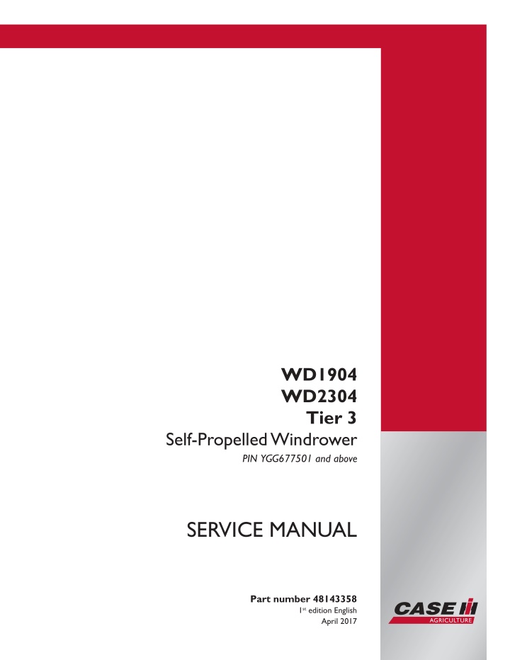
CASE IH WD1904 Tier 3 Self-Propelled Windrower Service Repair Manual Instant Download (PIN YGG677501 and above)
CASE IH WD1904 Tier 3 Self-Propelled Windrower Service Repair Manual Instant Download (PIN YGG677501 and above)
Download Presentation

Please find below an Image/Link to download the presentation.
The content on the website is provided AS IS for your information and personal use only. It may not be sold, licensed, or shared on other websites without obtaining consent from the author. If you encounter any issues during the download, it is possible that the publisher has removed the file from their server.
You are allowed to download the files provided on this website for personal or commercial use, subject to the condition that they are used lawfully. All files are the property of their respective owners.
The content on the website is provided AS IS for your information and personal use only. It may not be sold, licensed, or shared on other websites without obtaining consent from the author.
E N D
Presentation Transcript
WD1904 WD2304 Tier 3 Self-Propelled Windrower PIN YGG677501 and above SERVICE MANUAL Printed in U.S.A. Part number 48143358 1st edition English 2017 CNH Industrial America LLC. All Rights Reserved. Case IH is a trademark registered in the United States and many other countries, owned or licensed to CNH Industrial N.V., April 2017 its subsidiaries or affiliates.
Link Product / Engine Product Market Product North America Engine F4HE9687 WD1904 Tier 3, Canada [YGG677501 - ] WD2304 TIER 3, Canada [YGG677501 - ] North America F4HE9687 48143358 20/04/2017
Contents INTRODUCTION Engine....................................................................................... 10 [10.202] Air cleaners and lines .............................................................. 10.1 [10.218] Fuel injection system............................................................... 10.2 [10.400] Engine cooling system ............................................................. 10.3 [10.414] Fan and drive ...................................................................... 10.4 [10.250] Turbocharger and lines............................................................. 10.5 [10.304] Engine lubrication system.......................................................... 10.6 Front axle system ....................................................................... 25 [25.310] Final drives......................................................................... 25.1 Rear axle system........................................................................ 27 [27.550] Non-powered rear axle............................................................. 27.1 Hydrostatic drive......................................................................... 29 [29.100] Transmission and steering hydrostatic control..................................... 29.1 [29.130] Neutralizer plate assembly......................................................... 29.2 [29.202] Hydrostatic transmission ........................................................... 29.3 [29.218] Pump and motor components...................................................... 29.4 Brakes and controls .................................................................... 33 [33.110] Parking brake or parking lock ...................................................... 33.1 Hydraulic systems....................................................................... 35 [35.000] Hydraulic systems.................................................................. 35.1 [35.100] Main lift system..................................................................... 35.2 [35.105] Charge pump....................................................................... 35.3 [35.128] Auxiliary hydraulic function control................................................. 35.4 [35.220] Auxiliary hydraulic pump ........................................................... 35.5 [35.300] Reservoir, cooler, and filters........................................................ 35.6 48143358 20/04/2017
https://www.ebooklibonline.com Hello dear friend! Thank you very much for reading. Enter the link into your browser. The full manual is available for immediate download. https://www.ebooklibonline.com
[35.304] Combination pump units ........................................................... 35.7 [35.410] Header or attachment height system .............................................. 35.8 [35.415] Header or attachment tilting system ............................................... 35.9 [35.602] Header or attachment leveling system........................................... 35.10 [35.760] Header reverser drive............................................................ 35.11 [35.910] Head and header hydraulic drive ................................................ 35.12 Frames and ballasting................................................................. 39 [39.105] Lift arm ............................................................................. 39.1 [39.140] Ballasts and supports .............................................................. 39.2 Steering..................................................................................... 41 [41.101] Steering control .................................................................... 41.1 [41.200] Hydraulic control components...................................................... 41.2 [41.432] Autoguidance steering ............................................................. 41.3 Wheels...................................................................................... 44 [44.511] Front wheels........................................................................ 44.1 Cab climate control..................................................................... 50 [50.200] Air conditioning..................................................................... 50.1 Electrical systems....................................................................... 55 [55.670] Header leveling control............................................................. 55.1 [55.000] Electrical system ................................................................... 55.2 [55.100] Harnesses and connectors......................................................... 55.3 [55.015] Engine control system.............................................................. 55.4 [55.201] Engine starting system............................................................. 55.5 [55.301] Alternator........................................................................... 55.6 [55.302] Battery.............................................................................. 55.7 [55.202] Cold start aid ....................................................................... 55.8 [55.011] Fuel tank system ................................................................... 55.9 [55.010] Fuel injection system............................................................. 55.10 48143358 20/04/2017
[55.014] Engine intake and exhaust system............................................... 55.11 [55.013] Engine oil system ................................................................ 55.12 [55.640] Electronic modules............................................................... 55.13 [55.640] Electronic modules............................................................... 55.14 [55.019] Hydrostatic drive control system ................................................. 55.15 [55.522] Cab Power Take-Off (PTO) controls ............................................. 55.16 [55.031] Parking brake electrical system.................................................. 55.17 [55.512] Cab controls...................................................................... 55.18 [55.036] Hydraulic system control ......................................................... 55.19 [55.050] Heating, Ventilation, and Air-Conditioning (HVAC) control system............... 55.20 [55.047] Steering control system .......................................................... 55.21 [55.661] Cab header controls.............................................................. 55.22 [55.662] Header height control ............................................................ 55.23 [55.634] Merger electrical control system ................................................. 55.24 [55.785] Precision farming system ........................................................ 55.25 [55.911] Satellite navigation systems...................................................... 55.26 [55.518] Wiper and washer system........................................................ 55.27 [55.404] External lighting .................................................................. 55.28 [55.405] External lighting switches and relays ............................................ 55.29 [55.510] Cab or platform harnesses and connectors...................................... 55.30 [55.680] Autopilot/Autoguidance .......................................................... 55.31 [55.DTC] FAULT CODES.................................................................. 55.32 Platform, cab, bodywork, and decals............................................. 90 [90.124] Pneumatically-adjusted operator seat.............................................. 90.1 [90.150] Cab................................................................................. 90.2 [90.151] Cab interior......................................................................... 90.3 [90.154] Cab doors and hatches ............................................................ 90.4 48143358 20/04/2017
INTRODUCTION 48143358 20/04/2017 1
INTRODUCTION Foreword - Important notice regarding equipment servicing All repair and maintenance work listed in this manual must be carried out only by qualified dealership personnel, strictly complying with the instructions given, and using, whenever possible, the special tools. Anyone who performs repair and maintenance operations without complying with the procedures provided herein shall be responsible for any subsequent damages. The manufacturer and all the organizations of its distribution chain, including - without limitation - national, regional, or local dealers, reject any responsibility for damages caused by parts and/or components not approved by the manu- facturer, including those used for the servicing or repair of the product manufactured or marketed by the manufacturer. In any case, no warranty is given or attributed on the product manufactured or marketed by the manufacturer in case of damages caused by parts and/or components not approved by the manufacturer. The manufacturer reserves the right to make improvements in design and changes in specifications at any time without notice and without incurring any obligation to install them on units previously sold. Specifications, descriptions, and illustrative material herein are as accurate as known at time of publication but are subject to change without notice. In case of questions, refer to your CASE IH Sales and Service Networks. 48143358 20/04/2017 3
INTRODUCTION Safety rules Personal safety This is the safety alert symbol. It is used to alert you to potential personal injury hazards. Obey all safety messages that follow this symbol to avoid possible death or injury. Throughout this manual you will find the signal words DANGER, WARNING, and CAUTION followed by special in- structions. These precautions are intended for the personal safety of you and those working with you. Read and understand all the safety messages in this manual before you operate or service the machine. DANGER indicates a hazardous situation that, if not avoided, will result in death or serious injury. WARNING indicates a hazardous situation that, if not avoided, could result in death or serious injury. CAUTION indicates a hazardous situation that, if not avoided, could result in minor or moderate injury. FAILURE TO FOLLOW DANGER, WARNING, AND CAUTION MESSAGES COULD RESULT IN DEATH OR SERIOUS INJURY. Machine safety NOTICE: Notice indicates a situation that, if not avoided, could result in machine or property damage. Throughout this manual you will find the signal word Notice followed by special instructions to prevent machine or property damage. The word Notice is used to address practices not related to personal safety. Information NOTE: Note indicates additional information that clarifies steps, procedures, or other information in this manual. Throughout this manual you will find the word Note followed by additional information about a step, procedure, or other information in the manual. The word Note is not intended to address personal safety or property damage. 48143358 20/04/2017 4
INTRODUCTION Safety rules General safety rules Use caution when operating the machine on slopes. Raised equipment, full tanks and other loads will change the center of gravity of the machine. The machine can tip or roll over when near ditches and embankments or uneven surfaces. Only skilled operators who are familiar with all the controls and harvesting techniques should use the equipment. It is recommended to operate on cultivated land with slopes no greater than 26% ( 15 ) uphill and downhill. If necessary, when driving downhill change into a lower gear before starting the descent. Machine must be stopped to downshift into a lower gear. Never permit anyone other than the operator to ride on the machine. Never operate the machine under the influence of alcohol, drugs, or while otherwise impaired. Pay attention to overhead power lines and hanging obstacles. High voltage lines may require significant clearance for safety. Hydraulic oil or diesel fuel leaking under pressure can penetrate the skin, causing serious injury or infection. DO NOT use your hand to check for leaks. Use a piece of cardboard or paper. Stop engine, remove key and relieve the pressure before connecting or disconnecting fluid lines. Make sure all components are in good condition and tighten all connections before starting the engine or pressur- izing the system. If hydraulic fluid or diesel fuel penetrates the skin, seek medical attention immediately. Continuous long term contact with hydraulic fluid may cause skin cancer. Avoid long term contact and wash the skin promptly with soap and water. Keep clear of moving parts. Loose clothing, jewelry, watches, long hair, and other loose or hanging items can become entangled in moving parts. Wear protective equipment when appropriate. DO NOT attempt to remove material from any part of the machine while it is being operated or components are in motion. Make sure all guards and shields are in good condition and properly installed before operating the machine. Never operate the machine with shields removed. Always close access doors or panels before operating the machine. Dirty or slippery steps, ladders, walkways, and platforms can cause falls. Make sure these surfaces remain clean and clear of debris. A person or pet within the operating area of a machine can be struck or crushed by the machine or its equipment. DO NOT allow anyone to enter the work area. Raised equipment and/or loads can fall unexpectedly and crush persons underneath. Never allow anyone to enter the area underneath raised equipment during operation. Never operate engine in enclosed spaces as harmful exhaust gases may build up. Before starting the machine, be sure that all controls are in neutral or park lock position. Start the engine only from the operator s seat. If the safety start switch is bypassed, the engine can start with the transmission in gear. Do not connect or short across terminals on the starter solenoid. Attach jumper cables as described in the manual. Starting in gear may cause death or serious injury. Always keep windows, mirrors, all lighting, and Slow Moving Vehicle (SMV) emblem clean to provide the best possible visibility while operating the machine. 48143358 20/04/2017 5
SERVICE MANUAL Engine WD1904 Tier 3, Canada [YGG677501 - ] WD2304 TIER 3, Canada [YGG677501 - ] 48143358 20/04/2017 10
Engine - Air cleaners and lines Replace primary (outer) air filter The display will indicate when you must perform routine service for the air filter. Replace both the outer and inner filters annually. NOTICE: Do not clean the inner filter. 1. The air filter (1) is located under the right engine bay door. 1 NHIL14WR00357AA 2. To remove the element, release the three latches (1). 3. Remove the hose clamp (2) on the bottom of the cover. 4. Remove the hose (3) from the cover. 5. Pull the cover off. 2 NHIL14WR00357AA 6. Pull the outer filter (1) out. 3 10041166 48143358 20/04/2017 10.1 [10.202] / 3
Engine - Air cleaners and lines 7. Clean the inside of the air cleaner housing and cover using a damp, lint-free cloth. NOTICE: Do not remove or disturb the inner element (1). The inner element must be replaced if there is any sign of dirt on it. The inner element should not be cleaned, but only replaced. 4 10041167 8. Install the outer element (1). Push the element in all the way. 5 10041166 9. Install the cover at the angle at which it was removed. 10. Secure the cover with the three latches (1). 11. Install the hose (3) back onto the cover. 12. Secure the hose to the cover with hose clamp (2). 6 NHIL14WR00357AA 48143358 20/04/2017 10.1 [10.202] / 4
Engine - Air cleaners and lines Replace secondary (inner) air filter The display will indicate when you must perform routine service for the air filter. Replace both the outer and inner filters annually. NOTICE: Do not clean the inner filter. 1. Remove the outer filter as described in Replace pri- mary (outer) air filter (10.202) . 2. Pull the inner filter (1) out. Some wiggling may be nec- essary. 3. Clean the inside of the air cleaner housing and the cover with a damp, lint-free cloth. 4. Install the new inner filter. Push the filter in until it is seated. 5. Install the outer filter and close the housing as de- scribed in Replace primary (outer) air filter (10.202) . 1 10041425 48143358 20/04/2017 10.1 [10.202] / 5
Engine - Fuel injection system Fuel injection system - Test NA WD1904 Tier 3, Canada [YGG677501 - ] Fuel inlet restriction/air entering system 1 BAIL08CVT128ASA (1) 380100057 0 11 bar (0 160 psi) gauge and hose assembly (2) 380100056 0 100 kPa / 0 30 in / HG, 0 200 kPa / 0 30 in PSI Gauge Assembly (A) From fuel tank (B) Return to fuel tank NOTE: Use the contents of special tool 380140055 for these tests. 1. Install 380100056 at the inlet of the low pressure pump (after the primary filter). This test line contains a compound gauge 0 762 mm (0 30 in) of Hg vacuum and 0 2.07 bar (0 30 psi) positive pressure. This test line is con- structed with clear tubing to allow observation for air in the system. Operate the engine to purge air from the system which entered during gauge installation. 2. Install 380100057 between the outlet of the fuel filter and the inlet of the high pressure pump. This test line contains a pressure gauge 0 11 bar (0 160 psi). NOTE: The clear line could be left in place over night to check for a slow air ingress leak. 48143358 20/04/2017 10.2 [10.218] / 3
Engine - Fuel injection system 3. When air is no longer visible in the clear test line, mea- sure and record the operating pressure, while continu- ally observing for air in the fuel. Fuel Pressure Specifi- cation between Filter and High Pressure Pump: 5 bar (72 psi) minimum. Conditions: ________Gauge 1 ________ Gauge 2: Low idle; apply no load to the engine. ________Gauge 1 ________ Gauge 2: 1500 RPM apply no load to the engine. ________Gauge 1 ________ Gauge 2: High idle; apply load to the engine using the hydraulics (over relief), hydrostatic stall, converter stall, or dy- namometer. Load the engine to its rated rpm. 2 BAIL08CVT129FSA (1) 380100057 0 11 bar (0 160 psi) gauge and hose assembly (2) 380100056 0 100 kPa / 0 30 in / HG, 0 200 kPa / 0 30 in PSI Gauge Assembly (3) Primary Filter Outlet to Low Pressure Pump Inlet (4) High Pressure Pump Inlet from Fuel Filter Outlet (5) Secondary Fuel Filter (pressurized filter) (6) Secondary Fuel Filter Inlet (pressurized filter) (7) Primary Fuel Filter (suction filter) 48143358 20/04/2017 10.2 [10.218] / 4
Engine - Fuel injection system 4. If the fuel pressure at gauge (1) is below 5 bar (73 psi) at any time during the test, check or replace the follow- ing as needed: Fuel Pre-filter (if equipped). Some applications do not use a fuel pre-filter. Primary Fuel Filter The lines and connections from the fuel supply pump inlet back to the fuel tank, checking for damaged lines (kinks create restriction; rub marks may allow air to enter) and leakage at the Voss o-ring fittings. Fuel tank, clean as required. The fuel pick-up tube in the fuel tank. Check for cracks, plugging, or contact with the bottom/side- walls of the tank. The fuel tank cap. Be sure a vacuum is not being formed in the fuel tank. A vacuum at the tank would reduce the fuel supply pressure to the injection fuel pump inlet. Vacuum in the fuel tank might not be observable during short-term running. Check the valve at the fuel tank outlet (if equipped). Ensure that fuel supplied to and from the valve as- sembly is properly connected. 48143358 20/04/2017 10.2 [10.218] / 5
Engine - Fuel injection system Low pressure pump testing 3 BAIL08CVT130FSA (1) 380100057 0 11 bar (0 160 psi) gauge and hose assembly (2) Low Pressure Pump (3) 380100058 Plastic 2.0 l (4.2 US pt) container located not more than 1 m (3.3 ft) 48143358 20/04/2017 10.2 [10.218] / 6
Engine - Fuel injection system 5. If the pressure is still below 5 bar (73 psi) minimum, perform tests in steps 6 and 7. 6. Supply fuel from an alternate fuel source (a separate container, 380100058), located not more than 1 m (3.3 ft) below the engine with a known good supply line. This bypasses: The Fuel Tank, Inlet Lines and Connections, and Pre-Filter (if equipped). Connect a pressure gauge assembly 380100057 between the fuel filter outlet and the high pressure pump inlet. 7. The engine should start (at the first or second attempt) and then draw fuel from the external container. Check the fuel pressure at 1500 RPM. The reading on the fil- ter outlet pressure gauge should be higher than 5 bar (73 psi). If the pressure is lower than 5 bar (73 psi): Replace the fuel filter(s). Retest. If the pressure is still below 5 bar (73 psi), replace the low pressure pump. Retest. If the pressure is still below 5 bar (73 psi), the pressure regulator (part of the high pressure pump assembly) could be responsible, replace the high pressure pump. Pressure relief valve testing 4 BAIL08CVT131FSA (1) Fuel rail (2) Pressure Relief Valve Return Line Coupler 48143358 20/04/2017 10.2 [10.218] / 7
Engine - Fuel injection system 8. The Pressure Relief Valve is located at rear end of the fuel rail. This pressure relief valve protects the fuel system components from excessive pressure if: The Rail Pressure Sensor fails to signal the correct pressure to the ECU (Engine Control Unit). The High Pressure Flow Regulator, located at the pump, allows excessive pressure in the high pres- sure system. Check the ECU for: Fault codes related to over pressurization of the common rail, refer to: High Pressure Flow Regula- tor. 9. Disconnect the pressure relief valve return line and cap the line with 380100060 cap. Install 380100057 gauge and hose assembly on the relief valve to direct any leakage to container 380100062 if the relief valve is leaking. NOTE: Under normal circumstances fuel should not come out of the relief valve. 10. If the diagnostic system does not indicate a fault code and fuel is leaking from the pressure relief valve, re- place the pressure relief valve. High pressure flow regulator 5 BAIL08CVT132FSA (1) High Pressure Flow Regulator (Resistance Specification is 3.2 ) 48143358 20/04/2017 10.2 [10.218] / 8
Engine - Fuel injection system 11. TheHighPressureFlowRegulatorisanelectricalcon- trol located at the inlet of the high pressure pump. It regulates the amount of fuel supplied to the high pres- sure system based on control signals received from the ECU (by modulating the pulses sent to the internal solenoid). This is used to control the pressure within the fuel rail. The high pressure flow regulator is normally open. The high pressure pump is in maximum delivery mode if no control signal is sent by the ECU. 12. If the high pressure flow regulator has an open circuit (the flow regulator is disconnected, the harness is bro- ken, etc.) or a short circuit (resistance value is much lower than 3.2 ): The pump will be in maximum delivery mode and pressure in the rail will exceed 1700 bar (24650 psi) for a very short amount of time. The High pressure relief valve will open. The ECU sense the over pressure condition and store fault codes in the ECU memory. The engine will derate. 13. Check the resistance (on the ECU connector pins). The resistance specification is approximately 3.2 . 14. When in parameter mode on the Electronic Service Tool, the duty cycle reading indicates the position of the regulator. NOTICE: When all of the system components have been checked, inspect for the following symptoms: The duty cycle tends to fluctuate irregularly and the engine idle speed is irregular. The engine stalls when idling and no fault is stored in the ECU. Starting is difficult (takes longer than 4 seconds). Replace the high pressure flow regulator. 48143358 20/04/2017 10.2 [10.218] / 9
Engine - Fuel injection system Fuel injectors 6 BAIL08CVT133FSA (1) Return Line at Fuel Filter Base (disconnect and plug using 380100059) (2) Return Line Shown Disconnected and Capped ( 380100060) (3) Drain Line (use gauge and hose assembly 380100057 as the drain line) Shown connected to fuel return outlet on the cylinder head (4) 100 ml (3.4 US fl oz) Cup (380100062) 15. Engine load and rpm are controlled by the fuel injec- tors. The load requested by the operator is controlled by the throttle position and converted into a fuel quan- tity by the ECU. The ECU controls the amount and timing of the fuel injection (using current fuel rail pres- sure as a factor). Fuel injector mechanical problems: If the engine is difficult to start (excessive cranking time and no fault codes present): Warmengineto50 C(122 F)minimum. Checkfor excessive fuel return of the cylinder head injectors (with the engine running at low idle (no load - A/C etc.). Complete (A) and/or (B) as required. NOTE:Returnleakagecanbecheckedatvariouslocations (at the filter base or the cylinder head depending on ease of the connection. If excessive leakage is found, additional testing will be required to determine the exact location(s) of the leakage. Each fuel injector connector and the pres- sure relief valve could be a source of excessive return flow. More than one component could be responsible for exces- sive return. 48143358 20/04/2017 10.2 [10.218] / 10
Suggest: If the above button click is invalid. Please download this document first, and then click the above link to download the complete manual. Thank you so much for reading
Engine - Fuel injection system (A) - Disconnect the return line at the fuel filter base and plug (380100059) the filter port. Drain the fuel re- turn line at the filter head into a 100 ml (3.4 US fl oz) cup (380100062) and measure the amount of fuel that escapes from the drain line in one minute. Leakage should not exceed 80 ml (2.7 US fl oz) per minute with theenginerunningatlowidle. Ifleakageexceeds80 ml (2.7 US fl oz) retest as directed in Step (B) to determine location of leakage. (B) - Disconnect the return line on the engine cylinder head and cap ( 380100060 ) the line. Connect a drain line (use 380100057 as a drain line) to the fuel return outlet on the cylinder head and measure the amount of fuel that escapes from the cylinder head port in one minute using a 100 ml (3.4 US fl oz) cup (380100062). Leakage should not exceed 80 ml (2.7 US fl oz) per minute with the engine running at low idle. 7 BAIL08CVT134FSA (1) Injector (2) Injector Connector - Check the fuel injector end of the connector to make sure is not deformed. (3) Injector Connector Cylinder Head Location - Torque Specification is 45 55 Nm (33 41 lb ft) (4) Fuel Rail Outlet - Cap ( 380100061) each fuel rail outlet location; one at a time. (5) Interface location between injector and injector connector 48143358 20/04/2017 10.2 [10.218] / 11
https://www.ebooklibonline.com Hello dear friend! Thank you very much for reading. Enter the link into your browser. The full manual is available for immediate download. https://www.ebooklibonline.com


