Case Mw24c Wheel Loader Service Repair Manual Instant Download
Case Mw24c Wheel Loader Service Repair Manual Instant Download

Download Presentation

Please find below an Image/Link to download the presentation.
The content on the website is provided AS IS for your information and personal use only. It may not be sold, licensed, or shared on other websites without obtaining consent from the author. If you encounter any issues during the download, it is possible that the publisher has removed the file from their server.
You are allowed to download the files provided on this website for personal or commercial use, subject to the condition that they are used lawfully. All files are the property of their respective owners.
The content on the website is provided AS IS for your information and personal use only. It may not be sold, licensed, or shared on other websites without obtaining consent from the author.
E N D
Presentation Transcript
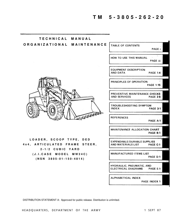
T M 5 - 3 8 0 5 - 2 6 2 - 2 0 T E C H N I C A L M A N U A L O R G A N I Z A T I O N A L M A I N T E N A N C E L O A D E R , S C O O P T Y P E , D E D 4 x 4 , A R T I C U L A T E D F R A M E S T E E R , 2 - 1 / 2 C U B I C Y A R D ( J . I . C A S E M O D E L M W 2 4 C ) ( N S N 3 8 0 5 - 0 1 - 1 5 0 - 4 8 1 4 ) DISTRIBUTION STATEMENT A: Approved for public release. Distribution is unlimited. 1 SEPT 87 HEA DQ UA RTERS, DEPA RTMENT O F THE A RMY
TM 5-3805-262-20 EXHAUST GASES CAN BE DEADLY Exhaust gases can produce symptoms of headache, dizziness, lOSS of muscular control, or coma. Permanent brain damage or death can result from severe exposure. You can insure your safety by following these rules: DON T operate the heater or engine in an enclosed area unless it is properly ventilated. DON-T drive with any of the loader-s inspection plates , cover plates, or the hood off unless necessary for maintenance. If you notice exhaust odors or exposure symptoms, IMMEDIATELY VENTILATE the area. If symptoms persist, remove the affected people and treat them: G Expose them to fresh air. If necessary, give artificial respiration. G Keep them warm. DON T permit physical exercise. Refer to FM 21-11, First Aid for Soldiers, for first aid treatment of injured personnel. ROTATING FAN BLADES Before working in area between radiator and engine, be sure engine is turned off. Failure to do so could cause serious injury to fingers or hand by rotating fan blade. If you injure your fingers or hand, obtain medical aid immediately. OIL UNDER PRESSURE Hydraulic reservoir is pressurized. hydraulic control valves before removing hydraulic reservoir fill cap. Failure to do so could cause serious injury or death. Shut off engine and operate RETAINING/SNAP RINGS UNDER SPRING TENSION Exercise care when removing retaining/snap rings. Some of these parts are under spring tension. Severe injury may result by the part striking your eye if you don t observe this precaution. If your eye is struck by a foreign object, seek medical aid immediately. a
Hello Thank you very much for your download. In the last page of this PDF document. There is a link. Please click on that link and return to our website. Then you can get the complete manual immediately. No need to wait. Thanks for continuing to read the documentation. Best wishes.
TM 5-3805-262-20 Toxic /FLAMMABLE Dry cleaning solvent P-D-680 used to clean parts is toxic and flammable. Wear protective goggles and gloves and use only in a well ventilated area. Avoid contact with skin, eyes and clothes and don t breathe vapors. Do not use near open flame or excessive heat and don t smoke when using it. Failure to do so could cause serious injury. If you become dizzy while using cleaning solvent, get fresh air and medical attention immediately. If contact with skin or clothes is made, flush with large amounts of water. If contact with eyes is made, wash eyes with water and get medical aid immediately. Starting fluid is toxic and highly flammable. Container is pressurized to act as an expellent. Don t heat container and don t discharge start- ing fluid in confined areas or near open flame. Don t discard used con- tainer in an open flame. To do any of the above will cause an explosion. Don t breathe ether vapor or allow ether to come in contact with your skin. To do so will cause severe injury or death. ELECTRICAL SHOCK HAZARD Always disconnect battery ground cable before working on electrical components of this equipment. Death or severe injury may result if you fail to observe this precaution. If you receive an electrical shock, seek medical aid immediately. HIGH VELOCITY AIR Compressed air used for cleaning purpose will not exceed 30 psi. Use only with effective chip guarding and personal protective equipment (goggles/shield, gloves, etc). Failure to do so could cause serious injury to eyes and possible blindness. foreign object is blown into your eyes, seek medical attention immediately. If you hurt your eyes or if a FALLING EQUIPMENT When using chain hoist to remove or install parts, be sure chain hoist is securely fastened to the part and that all slack in chain is taken up. Failure to do so could cause serious injury due to the part falling on you. If you are injured by falling equipment, obtain medical aid immediately. b
https://www.ebooklibonline.com Hello dear friend! Thank you very much for reading. Enter the link into your browser. The full manual is available for immediate download. https://www.ebooklibonline.com
TM 5-3805-262-20 NOISE HAZARD Noise level exceeds 85 dB when operating loader with cab windows open or performing maintenance with engine operating. All personnel shall wear a hearing protective device when operating loader with windows open or performing loader maintenance with engine operating to prevent hearing loss. EXPLOSIVE HAZARD Don t use jumper cables connected to battery terminals to start engine or charge batteries. Always use slave receptacle. Failure to do so could cause serious injury due to batteries exploding caused by improper con- nection of jumper cables to battery terminals. STEAM UNDER PRESSURE etely remov- burns due to seek medical Remove radiator cap slowly to relieve pressure before compl ing when engine is hot. Failure to do so could cause severe hot steam scalding You. If you are scalded by hot steam, aid immediately. TIRE INFLATION inflating tire. Failure to Check that tire is correctly mounted before do so may result in severe injury or death due to explosive separation of the tire and rim parts. If necessary, remove tire and install in a tire inflation cage. Always stand behind tire tread when inflating tire. Do not inflate tire more than 40 psi. To do so may result in severe injury or death due to explosive separation of tire and rim parts. Stand behind tire tread and be sure personnel are not standing at side of tire before adding air. Failure to do so could cause severe injury or loss of life due to explosive separation of tire and rim parts. c
TM 5-3805-262-20 TIRE DEFLATION Deflate tire completely before removing tire from rim. Refer to manual to completely deflate tire. Failure to follow this procedure could cause serious injury. If you are injured by not completely deflating tire, seek medical help immediately. JACKING LOADER Make sure that loader will not roll or shift and that transport/service link is engaged before jacking loader. Secure with chock blocks. Death or serious injury may result by your failure to follow this procedure due to loader turning and slipping off jack or jack stands. If you are injured, obtain medical help immediately. Before starting engine, check and be sure that transport/service link is in released position. Failure to do so will cause loss of steering con- trol which may result in serious injury or death and extensive property damage. Always use hand rails and steps when you mount or dismount loader. Don t use steering wheel or controls as a hand rail. Any other method of mounting or dismounting loader could make you slip and fall causing ser- ious injury to yourself. Before moving loader up ramps, remove all ice, oil or grease from ramp to prevent loader from falling and causing death or serious injury and extensive damage to loader. Tell personnel to move away from loader. Don t allow personnel in or near the loader when it is being towed the engine stopped. To do so could cause serious injury or death. with d
TM 5-3805-262-20 Diesel fuel is highly combustible. Do not smoke or allow open flames or sparks into the area. Death or severe injury may result if personnel fail to observe this precaution. If you are burned, obtain medical aid immediately. Before performing any loader maintenance that requires servicing in area between front and rear chassis, be sure that transport/service link is engaged. Failure to do so could cause serious injury or death due to chassis pivoting and crushing you when you are working in area between front and rear chassis. Whenever a component or line in the brake system is disconnected for servicing, the air must be bled from the brake system. Failure to do so could cause serious injury or death due to loss of braking control. e
TM 5-3805-262-20 Left Front View Right Rear View MW24C Loader f
*TM 5-3805-262-20 HEADQUARTERS DEPARTMENT OF THE ARMY Washington D.C., 01 September 1987 TECHNICAL MANUAL NO. 5-3805-262-20 ORGANIZATIONAL MAINTENANCE LOADER, SCOOP TYPE, DED, 4 X 4, ARTICULATED FRAME STEER, 2-1/2 CUBIC YARD (J.I.CASE MODEL MW24C) (NSN 3805-01-150-4814) REPORTING ERRORS AND RECOMMENDING IMPROVEMENTS You can help improve this publication. If you find any errors, or if you would like to recommend any improvements to the proce- dures in this publication, please let us know. The preferred method is to submit your DA Form 2028 (Recommended Changes to Publications and Blank Forms) through the Internet, on the Army Electronic Product Support (AEPS) website. The Internet address is https://aeps.ria.army.mil. The DA Form 2028 is located under the Public Applications section in the AEPS Public Home Page. Fill out the form and click on SUBMIT. Using this form on the AEPS will enable us to respond quicker to your comments and better manage the DA Form 2028 program. You may also mail, E-mail, or fax your comments or DA Form 2028 directly to the U.S. Army TACOM Life Cycle Management Command. The postal mail address is U.S. Army TACOM Life Cycle Manage- ment Command, ATTN: AMSTA-LC-LMPP/TECH PUBS, 1 Rock Island Arsenal, Rock Island, IL 61299-7630. The E-mail address is tacomlcmc.daform2028@us.army.mil. The fax number is DSN 793-0726 or Commercial (309) 782-0726. TABLE OF CONTENTS Page INTRODUCTION. . . . . . . . . . . . . . . . . . . . . . . . . . . . . . . . . . . . . . . . . . . . . . . . . . . . . . . . . . . . . . . . . 1-1 Chapter Overview . . . . . . . . . . . . . . . . . . . . . . . . . . . . . . . . . . . . . . . . . . . . . . . . . . . . . . . . . . . . . . . . . 1-1 Section I General Information. . . . . . . . . . . . . . . . . . . . . . . . . . . . . . . . . . . . . . . . . . . . . . . . . . . . . . . . 1-1 Section II Equipment Description and Data . . . . . . . . . . . . . . . . . . . . . . . . . . . . . . . . . . . . . . . . . . . . . . 1-4 Section III Principles of Operation. . . . . . . . . . . . . . . . . . . . . . . . . . . . . . . . . . . . . . . . . . . . . . . . . . . . . 1-15 CHAPTER 2 MW24C LOADER MAINTENANCE . . . . . . . . . . . . . . . . . . . . . . . . . . . . . . . . . . . . . . . . . . . . . . . . . 2-1 Chapter Overview . . . . . . . . . . . . . . . . . . . . . . . . . . . . . . . . . . . . . . . . . . . . . . . . . . . . . . . . . . . . . . . . . 2-1 Section I Service Upon Receipt. . . . . . . . . . . . . . . . . . . . . . . . . . . . . . . . . . . . . . . . . . . . . . . . . . . . . . . 2-1 Section II Preventive Maintenance Checks and Services (PMCS). . . . . . . . . . . . . . . . . . . . . . . . . . . . . 2-6 Section III Movement to a New Work Site . . . . . . . . . . . . . . . . . . . . . . . . . . . . . . . . . . . . . . . . . . . . . . 2-11 CHAPTER 3 TROUBLESHOOTING . . . . . . . . . . . . . . . . . . . . . . . . . . . . . . . . . . . . . . . . . . . . . . . . . . . . . . . . . . . . 3-1 Chapter Overview . . . . . . . . . . . . . . . . . . . . . . . . . . . . . . . . . . . . . . . . . . . . . . . . . . . . . . . . . . . . . . . . . 3-1 Section I Troubleshooting Symptom Index. . . . . . . . . . . . . . . . . . . . . . . . . . . . . . . . . . . . . . . . . . . . . . 3-1 Section II Troubleshooting . . . . . . . . . . . . . . . . . . . . . . . . . . . . . . . . . . . . . . . . . . . . . . . . . . . . . . . . . . . 3-6 Section II Troubleshooting using STE/ICE (Simplified Test Equipment for Internal Combustion Engines) . . . . . . . . . . . . . . . . . . . . . . . . . . . . . . . . . . 3-200 CHAPTER 4 ENGINE, FUEL, EXHAUST, AND COOLING SYSTEMS MAINTENANCE. . . . . . . . . . . . . . . . . 4-1 Chapter Overview . . . . . . . . . . . . . . . . . . . . . . . . . . . . . . . . . . . . . . . . . . . . . . . . . . . . . . . . . . . . . . . . . 4-1 CHAPTER 5 ELECTRICAL SYSTEM MAINTENANCE . . . . . . . . . . . . . . . . . . . . . . . . . . . . . . . . . . . . . . . . . . . . 5-1 Chapter Overview . . . . . . . . . . . . . . . . . . . . . . . . . . . . . . . . . . . . . . . . . . . . . . . . . . . . . . . . . . . . . . . . . 5-1 CHAPTER 6 POWER TRAIN MAINTENANCE . . . . . . . . . . . . . . . . . . . . . . . . . . . . . . . . . . . . . . . . . . . . . . . . . . . 6-1 Chapter Overview . . . . . . . . . . . . . . . . . . . . . . . . . . . . . . . . . . . . . . . . . . . . . . . . . . . . . . . . . . . . . . . . . 6-1 * This technical manual, in combination with TM 5-3805-262 series (-10, -24P, and -34) supersedes TM 5-3805-262-14&P-1 and TM 5-3805-262-14&P-2 in its entirety CHAPTER 1 Change 2i
TM 5-3805-262-20 TABLE OF CONTENTS Page CHAPTER 7 BRAKE SYSTEM MAINTENANCE Chapter Overview 7-1 7-1 . . . . . . . . . . . . . . . . . . CHAPTER 8 WHEELS AND STEERING SYSTEM MAINTENANCE Chapter Overview . . 8-1 8-1 . . . . . . . . . . . . . . . . . FRAME AND TOWING ATTACHMENTS AND BODY AND CAB MAINTENANCE . . Chapter Overview . . . . . . . . . . . . . . . . . . . . . . CHAPTER 9 9-1 9-1 ACCESSORY ITEMS AND DATA PLATES MAINTENANCE Chapter Overview 10-1 10-1 CHAPTER 10 . . . . . . . . . . . . . . . . HYDRAULIC SYSTEM Chapter Overview MAINTENANCE 11-1 11-1 CHAPTER 11 CHAPTER 12 SIGNALING DEVICES AND LOADER BUCKET ASSEMBLY MAINTENANCE . . . Chapter Overview . . . . . . . . . . . . . . . . . . . . . . . . . . . 12-1 12-1 APPENDIX A A-1 APPENDIX B B-1 APPENDIX C C-1 APPENDIX D D-1 APPENDIX E E-1 APPENDIX F TORQUE LIMITS F-1 METRIC CONVERSIONS . . . . . . . . . . . . . . . . . . . . . . . . . . . . . . . . . . . . . . . . . . . . . . APPENDIX G G-1 Glossary 1 GLOSSARY ALPHABETICAL INDEX Index 1 i i Change 1
TM 5-3805-262-20 HOW TO USE THIS MANUAL This manual is designed to help you operate and maintain the MW24C loader. It s di- vided into chapters, sections, and appendices. Chapter 1 contains general informa- tion, equipment description and data, and principles of operation of the loader. Chapter 2 contains data applicable to service to be performed on receipt of the loader, FMCS, and procedures to be followed when moving to a new work site. Chapter 3 contains troubleshooting information consisting of a symptom index and detailed troubleshooting procedures. Chapters 4 through 12 contain detailed maintenance pro- cedures. Appendices contain supplemental information which you require to maintain the loader. Procedures in this manual tell you several things: how to perform your PMCS and how often what tools you need to perform the job materials or parts required . . . . . . . . . . . . . . . . . . . what condition the loader is to be in before work is started. In addition to the text, you ll have either an assembled view or an exploded view illustration of the associated parts. Sometimes, the illustration will be keyed by an arrow to an overall view of the loader to help you determine the approximate lo- cation of the parts. The illustration is keyed to the text by numbers and shows you how to take the part off and put it on. The following problem will show you some of the features of this manual: PROBLEM An operator brings his loader into the shop with an engine problem: The engine stalls frequently or doesn t develop full power. The best way to solve his problem is by using your manual. This is what you do: 1. How do you start? Look at the cover of the manual. On the cover you ll find a listing for TROUBLESHOOTING SYMPTOM INDEX. It tells you to go to page 3-1. To find page 3-1 fast, open the manual by using the black tab that lines up with the listing on the cover. 2. What kind of problem do you have? Find it in the symptom index. The symptom index is a list of problems covered by the section. It tells you that your problem "engine stalls frequently or doesn t develop full power" is cover- ed in paragraph 3-4 MALFUNCTION entry number 6 on page 3-23. Directly beneath the MALFUNCTION entry number you ll also see a number enclosed in parentheses. This num- ber refers to the paragraph and MALFUNCTION entry number where troubleshooting your problem is also covered using STE/ICE equipment if available. This troubleshooting using STE/ICE is covered on page 3-225. iii
TM 5-3805-262-20 HOW TO USE THIS MANUAL (CONT) 3. How do you determine what is causing the problem? GO to page 3-23 or page 3-225 if you have STE/ICE, MALFUNCTION entry number 6. There you ll find the troubleshooting procedures you ll need. The procedure has columns with the headings MALFUNCTION, TEST OR INSPECTION, and CORRECTIVE ACTION. Starting at step 1, read the procedure. Each step tells you what to do and what to look for. Follow the steps, in order, until you find your problem. When you find the problem, the CORRECTIVE ACTION column will tell you how to fix it. 4. Let s assume you ve found that the air compressor is bad causing excessive drag on the engine. The procedure tells you to go to page 7-88. The procedure contains all the information you need to replace the air compressor. First check the intro- ductory material. It tells what you ll need before you start the job. Within the de- tailed procedural text are illustrations showing you how to take out the air com- pressor and how to put it back in. 5. If on the other hand, you know what the problem is and is cause, refer to the alphabetical index located at the rear of this manual and find the name of the part to be replaced and its page number where maintenance procedures will be found. For example, the engine is overheating and on filling the radiator with water you see that water is pouring out the bottom radiator hose indicating that the hose requires replacement. Refering to the alphabetical index under the listing hoses, cooling system, page 4-74 is referenced. Turn to this page for hose removal procedure and following page(s) for installation procedure. This manual has been designed so that you can quickly locate data you are looking for. Either look in the ALPHABETICAL INDEX for the subject matter, refer to the front cover index, table of contents, chapter index, or section index to locate the data. iv
TM 5-3805-262-20 CHAPTER 1 INTRODUCTION CHAPTER OVERVIEW The purpose of this chapter is to provide you with standard data requir- ed in all manuals, to familiarize you with the purpose and capabilities of the vehicle and to give you a brief description of its different sys- tems and components. Index Page Title Section I II III General Information . . . . . . . . . . . . . . . . . . . . . . . . . . . . . . . . . . . . . . . . . . . 1-1 Equipment Description and Data . . . . . . . . . . . . . . . . . . . . . . . . . . . . . . . . 1-4 Principles of Operation . . . . . . . . . . . . . . . . . . . . . . . . . . . . . . . . . . . . . . . 1-15 Section I. GENERAL INFORMATION Para Para Reporting Recommendations (EIR) . . . . . . . . . 1-7 Warranty Information . . . . . . . . . . . . . 1-8 Orientation . . . . . . . . . . . . . . . . . . . . . . 1-9 Common Tools and Equipment . . . . . . . . . . . . . . . . . . . . . Special Tools, TMDE, and Support Equipment . . . . . . . . . . . . . . . . . . . . . Repair Parts . . . . . . . . . . . . . . . . . . . . . Modification. . . . . . . . . . . . . . . . . . . . . . . . . Equipment Improvement Scope . . . . . . . . . . . . . . . . . . . . . . . . . . . . 1-1 Maintenance Forms, Records, and Reports . . . . . . . . . . . . . . . . . . . . . . . 1-2 Destruction of Army Materiel to Prevent Enemy Use . . . . . . . . . . . . . 1-3 Preparation for Storage or Shipment 1-4 Quality Assurance/Quality Control (QA/QC) Official Names and Nomenclature . . 1-6 1-10 1-5 1-11 1-12 1-12.1 NOTE The equipment described herein is non-metric and does not require metric common or special tools; therefore, metric units are not supplied. Tac- tical instructions for sake of clarity will also remain non-metric. 1-1. a. Type Organizational Maintenance Manual. of Manual. b. Model Number and Equipment Name. Steering 4 by 4 Diesel Engine Driven Scoop Type Loader. MW24C 2-1/2 Cubic Yard Articulated Frame c. Purpo se of Equipment. and excavating undisturbed and compacted soil. Unit also used as a clamshell to handle irregular shaped objects, as a dozer for general bulldozer work, and as a scraper. Loading trucks from stockpiles, stockpiling materiel, 1-1
TM 5-3805-262-20 1-2. MAINTENANCE FORMS, RECORDS, AND REPORTS Department of the Army forms and procedures used for equipment maintenance will be those prescribed by DA PAM 738-750, The Army Maintenance Management System (TAMMS). 1-3. DESTRUCTION OFARMYMATERIEL TOPREVENTENEMYUSE Refer to TM 750-244-6. 1-4. PREPARATION FOR STORAGE OR SHIPMENT Refer to TM 5-3805-262-10 for preparation for storage and page 2-13 of this manual for preparation for air transport instructions. 1-5. QUALITY ASSURANCE/QUALITY CONTROL Quality assurance and quality control shall be in accordance with MIL-STD-109 and MIL-M-38784. 1-6. OFFICIAL NAMESAND NOMENCLATURE The nomenclature, names, and designations used in this manual are in accordance with MIL-HDBK-63038-2 . 1-7. REPORTING EQUIPMENT IMPROVEMENT RECOMMENDATIONS (EIR) If your MW24C loader needs improvement, let us know. Send us an EIR. You, the user, are the only one who can tell us what you don-t like about your equipment. Let us know why you don t like the design. Put it on an SF 368 (Quality Deficiency Report). Commander, US Army Tank-Automotive Command, Mail it to us at: ATTN: AMSTA-MV, Warren, MI 48397-5000. We ll send you a reply. 1-8. WARRANTY INFORMATION The MW24C loader is warranted by J.I.Case Company, Racine, Wisconsin for 15 months or 1500 hours of operation, whichever occurs first. Warranty starts on the date found on DA Form 2408-9 in the logbook and/or the equipment warrenty data plate. Report all defects in material or workmanship to your supervisor who will take appropriate action. 1-9. ORIENTATION The loader bucket is mounted at the front of the MW24C and the engine faces the rear. Controls for operating the bucket (lift, tilt, clam) are located to the right when you are sitting in the operator-s seat. All references to right, left, front, or rear are from your viewpoint when you re sitting in the operator s seat. 1-10. COMMON TOOLS AND EQUIPMENT For authorized common tools and equipment refer to the Modified Table of Organiza- tion and Equipment (MTOE) applicable to your unit. 1-2
TM 5-3805-262-20 1-11. SPECIAL TOOLS, TMDE, AND SUPPORT EQUIPMENT No special tools are required. Tools, TMDE, and support equipment are listed in Section III of Appendix C. 1-12. REPAIR PARTS Repair parts are listed and illustrated in TM 5-3805-262-24P covering organizational, for the MW24C loader. the repair parts and special tools list direct support, and general support parts 1-12.1 MODIFICATIONS Refer to DAPAM 310-l and DA PAM750-10 for all published ModificationWork Orders which apply to the MW24C Scoop Loader. Refer to Department of the Army Modification Work Order MW05-3805-262-25- 001 (effective 1988) for Installation of Alcohol Evaporator. 1-3
TM 5-3805-262-20 Section II. EQUIPMENT DESCRIPTION AND DATA Para Equipment Characteristics, Capabilities, and Features . . . . . . . . . . . . . . . . . . . . . . . . . . . . . . . . . . . . . 1-13 Location and Description of Major Components and Plates . . . . . . . . . . . . . . . . . . . . . . . . . . . . . . . . . 1-14 Equipment Data . . . . . . . . . . . . . . . . . . . . . . . . . . . . . . . . . . . . . . 1-15 Safety, Care, and Handling . . . . . . . . . . . . . . . . . . . . . . . . . . 1-16 1-13. EQUIPMENT CHARACTERISTICS, CAPABILITIES, AND FEATURES Loading trucks and railcars from stockpiles, stock- a. Purpose of MW24C Loader. piling materiel, and excavating undisturbed and compacted soil. Unit also used as a clamshell to handle irregular shaped objects, as a dozer for general bulldozer work, and as a scraper. b. Capabilities and Features. (1) Two and one-half yard capacity bucket. (2) Operates over rough terrain. (3) Four speed ranges in forward; (4) Declutch pedal disengages transmission during loader operation to provide maximum hydraulic power when needed. (5) Diesel engine driven. (6) Power steering. (7) Power assisted air over hydraulic brakes. (8) Enclosed operator s compartment. (9) Auxiliary steering automatically cuts-in if primary steering is disabled. (10) Bucket height control to automatically stop loader lift arms at a prese- lected dump height. (11) Bucket return-to-dig control to automatically return bucket to preselected position. (12) Four-in-one bucket used as a scraper, blade, clamshell, or standard buck- et . (13) Ford depths up to 30 inches. (14) Collapsible steering wheel for air transport. two speed ranges in reverse. 1-14. LOCATION AND DESCRIPTION OF MAJOR COMPONENTS AND PLATES a. Location and Description of Major Components. ENGINE. J.I.Case Model A504BD Diesel engine having a displacement of 504 cubic in- ches. Accessories mounted on and considered a part of the engine include the alter- nator, air compressor, starting motor, fuel injection pump, and fuel filters. FUEL SYSTEM. Consists of fuel injectors, fuel injection pump, electric fuel pump, air cleaner, fuel filters, and cold start kit. EXHAUST SYSTEM. Consists of muffler and exhaust pipe. Muffler mounted on top of en- gine. COOLING SYSTEM. Includes radiator mounted in rear of loader, thermostat and housing, engine driven water pump, and fan. 1-4
TM 5-3805-262-20 1-14. a. Location and Description of Major Components. ELECTRICAL SYSTEM, 24 volt, negative ground, Includes engine driven alternator, starter motor, instrument panels, light system, and two 12 volt batteries connected in series, BRAKES. Disk brakes, air over hydraulic. Air actuated drum type parking brake locat- ed on transmission output shaft. STEERING SYSTEM. Consists of steering wheel, steering column and gear, and two steering cylinders. Power assist provided by hydraulic pump mounted on and driven by transmission. Also includes auxiliary steering system. FRAME AND TOWING ATTACHMENTS. Two section frame consisting of front and rear chas- sis; drawbar pin located at rear of loader. SIGNALING DEVICES, Consists of back-up alarm and turn signals. Back-up,alarm located at rear of loader; sounds when transmission is shifted into reverse. Turn signals lo- cated at top of cab; turn signal switch mounted on steering column. 1-5
TM 5-3805-262-20 1-14. LOCATION AND DESCRIPTION OF MAJOR COMPONENTS AND PLATES (CONT) a. Location and Description of Major Components (Cont). TRANSMISSION AND DRIVE SHAFTS. Four speeds in forward and two speeds in reverse. Has declutch feature which permits neutralizing transmission. Three drive shafts used to transmit power to front and rear axles. AXLES AND WHEELS. Standard planetary axles; pneumatic tires. CAB. Fully enclosed and removable for shipment purposes when necessary. With doors, windows, and front and rear windshields. ACCESSORIES. Includes air horn and control valve, windshield washer and wiper, out- side mirrors, heater, and fan defrosters. HYDRAULIC SYSTEM. Consists of hydraulic main pump assembly/steering pump, control valve assembly, hydraulic cylinders (lift arm, bucket tilt, and clam), hydraulic re- servoir, and hydraulic filter. EARTHMOVING COMPONENTS. Includes bucket lift arms and pivot assemblies and loader bucket assembly. b . Location of Identification, Instruction, and Warranty Plates. For location of identification, instruction, and warranty plates, refer to illustrations on following pages. 1-6
TM 5-3805-262-20 1-14. LOCATION AND DESCRIPTION OF MAJOR COMPONENTS AND PLATES (CONT) b. Location of Identification, Instruction, and Warranty Plates (Cont). 1-7
TM 5-3805-262-20 1-14. b. Location of Identification, Instruction, and Warranty Plates (Cont). 1-8
TM 5-3805-262-20 1-14. b. Location of Identification, Instruction, and warranty plates (Cont). . 1-9
TM 5-3805-262-20 1-15. EQUIPMENT DATA Equipment data is tabulated below. Manufacturer . . . . . . . . . . . . . . . . . . . . . . . . . . . . . . . . . . . . . . . . . . . . . . . . . . . . . . . . . . . . . J.I. Case Model . . . . . . . . . . . . . . . . . . . . . . . . . . . . . . . . . . . . . . . . . . . . . . . . . . . . . . . . . . . . . . MW24C DIMENSIONS AND WEIGHT Overall operating height (A) . . . . . . . . . . . . . . . . . . . . . . . . . . . . 16 feet, 1-1/2 inches Dump clearance at maximum height, 45 degrees dump (B) . . . . . . . . . . . . . . . . . . . . 9 feet Dump reach at maximum height, 45 degrees dump (C) . . . . . . . . . . . . . . . . 3 feet, 1 inch Dump reach at 7 feet dump height, 45 degrees dump (D) . . . . . . . . . . 4 feet, 5 inches Height to bucket hinge pin (E) . . . . . . . . . . . . . . . . . . . . . . . . . . . . Maximum shipping height (F) Overall length, bucket on ground (G) . . . . . . . . . . . . . . . . . . . . . . Overall width Wheel base (H) Tire tread Ground clearance (I) Height to top of steering wheel (J) Overall height without cab Width overtires . . . . . . . . . . . . . . . . . . . . . . . . . . . . . . . . . . . . . . . . . . . . . . . . . . . . . 100 inches Total weight Front axle weight Rear axle weight . . . . . . . . . . . . . . . . . . . . . . . . . . . . . . . . . . . . . . . . . . . . . . . . . . 13,150 pounds Center of gravity location . . . . . . . . . . . . . . . . . . . . . . . . . . . . . . . . . . . . . . 44 inches high; 12 feet, 2-1/2 inches 10 feet, 10-1/2 inches 22 feet, 5-1/2 inches 94-1/2 inches 10 feet, 1-1/2 inches 77 inches 16 inches 106-1/2 inches 106-1/2 inches 25,900 pounds 12,750 pounds 61.7 inches back from center of front axle 1-10
TM 5-3805-262-20 1-15. EQUIPMENT DATA (CONT) CAPACITIES Cooling system . . . . . . . . . . . . . . . . . . . . . . . . . . . . . . . . . . . . . . . . . . . . Cold weather protection . . . . . . . . . . . . . . . . . . . . 50/50 solution 11.25 gallons of water and ethylene glycol (antifreeze) 58 gallons Fuel tank. . . . . . . . . . . . . . . . . . . . . . . . . . . . . . . . . . . . . . . . . . . . . . . . . . Engine crankcase . . . . . . . . . . . . . . . . . . . . . . . . . . . . . . . . . . . . . . . . . . . . . . 18 quarts refill; 20 quarts with filter change Transmission . . . . . . . . . . . . . . . . . . . . . . . . . . . . . . . . . . . . . . . . . . . . . . . . 7.5 gallons refill; 9 gallons total system capacity Axles (each) Front differential carrier . . . . . . . . . . . . . . . . . . . . . . . . . . . . . . . . . . . . . . . . . . 26 quarts Rear differential carrier . . . . . . . . . . . . . . . . . . . . . . . Planetary ends (each) . . . . . . . . . . . . . . . . . . . . . . . . . . . Hydraulic reservoir . . . . . . . . . . . . . . . . . . . . . . . . . . . . . . . 20 quarts 3.5 quarts 17 gallons refill; total system capacity . . . . . . . gallons 29 PERFORMANCE SPEEDS (MPH) Forward 1st low range . . . . . . . . . . . . . . . . . . . . . . . . . . . . . . . . . . . . . . . . . . . . . . . . . . . . . . . . . . . . . 2.6 2nd low range . . . . . . . . . . . . . . . . . . . . . . . . . . . . . . . . . . . . . . . . . . . . . . . . . . . . . . . . . . . . . 6.5 3rd high range 4th high range Reverse 1st 2nd 11.4 22.2 . . . . . . . . . . . . . . . . . . . . . . . . . 3.6 . . . . . . . . . . . . . . . . . . . . . . . . . 8.7 . . . . . . . . . . . . . . . . . . . . . . Diesel 4 Stroke Cycle, Valve-in-Head Engine Type Firing Order Bore . . . . . . . . . . . . . . . . . . . . . . . . . . . . . . . . . . . . . . . . . . . . . . . . . . . . . . . . . . . . . . . . . . 4-5/8 inches Stroke . . . . . . . . . . . . . . . . . . . . . . . . . . . . . . . . . . . . . . . . . . . . . . . . . . . . . . . . . . . . . . . . . . . . 5 inches Piston Displacement . . . . . . . . . . . . . . . . . . . . . . . . . . . . . . . . . . . . . . . . . . . . . . . 504 Cubic Inches 6 Cylinder, 1-5-3-6-2-4 Compression Ratio 16.5 to 1 No Load Governed Speed . . . . . . . . . . . . . . . . . . . . . . . . . . . . . . . . . . . . . . . . . . . . 2330 to 2370 rpm Rated Engine Speed . . . . . . . . . . . . . . . . . . . . . . . . . . . . . . . . . . . . . . . . . . . . . . . . . . . . . . 2200 rpm Engine Idling Speed . . . . . . . . . . . . . . . . . . . . . . . . . . . . . . . . . . . . . . . . . . . . . . . . . 725 to775rpm Exhaust Valve Rotators . . . . . . . . . . . . . . . . . . . . . . . . . . . . . . . . . . . . . . . . . . . . . . . Positive Type Valve Tappet Clearance (Exhaust) (Intake) Cranking Motor . . . . . . . . . . . . . . . . . . . . . . . . . . . . . . . . . . . . . . . . . . . . . 24 Volt Negative Ground Thermostat Operating Range . . . . . . . . . . . . . . . . . . . . . . . . . . 175 degrees F to 202 degrees F Cooling System . . . . . . . . . . . . . . . . . . . . . . . . . . . . . . . . . . . . . Air, water with lube oil cooler .025 inch .015 inch ENGINE LUBRICATING SYSTEM Oil Pressure . . . . . . . . . . . . . . . . . . . . . . . . . . . . . . . . . . 45 to 55 Pounds with Engine Warm and Operating at Rated Engine Speed 1-11
TM 5-3805-262-20 1-15. ENGINE LUBRICATING SYSTEM (CONT) Type System . . . . . . . . . . . . . . . . . . . . . . . . . . . . . . . . . . . . . . . . . Pressure and Spray Circulation Oil Pump . . . . . . . . . . . . . . . . . . . . . . . . . . . . . . . . . . . . . . . . . . . . . . . . . . . . . . . . . . . . . . . .. Gear Type Oil Filter . . . . . . . . . . . . . . . . . . . . . . . . . . . . . . . . . . . . . . . . . . . . . . . . . .. Full Flow Turn on Type FUEL SYSTEM Fuel Injection Pump . . . . . . . . . . . . . . . . . . . . . . . . Robert Bosch, Type PES Multiple Plunger Pump Timing . . . . . . . . . . . . . . . . . . . . . . . 27 Degrees Before Top Dead Center (Port Closing) 1st Stage Fuel Filter . . . . . . . . . . . . . . . . . . . . . . . . . . . . . . . . . . . . . .. Full Flow Turn on Type 2nd Stage Fuel Filter . . . . . . . . . . . . . . . . . . . . . . . . . . . . . . . . . . . . . . . Full Flow Turn on Type Operating Pressure . . . . . . . . . . . . . . . . . . . . . . . . . . . . . . . . . . . . . . . . . . . . . . . . . . . . 20 to 30 psi ALTERNATOR Manufacturer . . . . . . . . . . . . . . . . . . . . . . . . . . . . . . . . . . . . . . . . . . . . . . . . . . . . . . . . . . . . Delco-Remy Part Number . . . . . . . . . . . . . . . . . . . . . . . . . . . . . . . . . . . . . . . . . . . . . . . . . . . . . . . . . . . . . . . . 1100077 Rating . . . . . . . . . . . . . . . . . . . . . . . . . . . . . . . . . . . . . . . . . . . . . . . . . . . . . . . . . . . . . . . . . . . 65 ampere AIR COMPRESSOR Manufacturer . . . . . . . . . . . . . . . . . . . . . . . . . . . . . . . . . . . . . . . . . . . . . . . . . . . . . . . . . . Midland Ross Part Number . . . . . . . . . . . . . . . . . . . . . . . . . . . . . . . . . . . . . . . . . . . . . . . . . . . . . . . . . . . . . . .. N5303AA Number of Cylinders . . . . . . . . . . . . . . . . . . . . . . . . . . . . . . . . . . . . . . . . . . . . . . . . . . . . . . . . . . . . . . 2 RADIATOR Manufacturer . . . . . . . . . . . . . . . . . . . . . . . . . . . . . . . . . . . . . . . . . . . . . . . . . . . . . .. General 22-4173 Young E299000 ELECTRICAL SYSTEM Electrical system voltage . . . . . . . . . . . . . . . . . . . . . . . . . . . . . . . . . . . . . . . . . . . . . . . . . 24volts Batteries . . . . . . . . . . . . . . . . . . . . . . . . . . . . . . . . . . . . . . . . . . . . . . . . . . . . . . . . . . . . . . (2) 12 volt Replacement Bulbs Warning lamp for hydraulic filters . . . . . . . . . . . . . . . . . . . . . . . . . . . . . . . . . . . . . . . . 1895R Cab lamp Stop and tail lamp . . . . . . . . . . . . . . . . . . . . . . . . . . . . . . . . . . . . . . . . . . . . . . . . . . . . . . . . . 1683 Instrument panel lamp Directional and flasher lamp . . . . . . . . . . . . . . . . . . . . . . . . . . . . . . . . . . . . . . . . . . . . . . . . 307 Driving lamps . . . . . . . . . . . . . . . . . . . . . . . . . . . . . . . . . . . . . . . . . . . . . . . . . . . . . . . . . . . . . . 4880 Flood lamps . . . . . . . . . . . . . . . . . . . . . . . . . . . . . . . . . . . . . . . . . . . . . . . . . . . . . . . . . . . . . ...4578 Instrument cluster lamps . . .. . . . . . .. . . . . . . . . . . . . . . . . . . . . . . . . . . . .. . . . . . . . . 194 Bulb Number 93 or 1591 363 BUCKET Width SAE Rated Capacity . . . . . . . . . . . . . . . . . . . . . . . . . . . . . . . . . . . . . . . . . . . . . . . . . . . . . . . 2.5 yards 104 inches HYDRAULIC SYSTEM Reservoir . . . . . . . . . . . . . . . . . . . . . . . . . . . . . . . . . . . . . . . . . . . . . . . . . . Positive pressurization Control Valve Manufacturer . . . . . . . . . . . . . . . . . . . . . . . . . . . . . . . . . . . . . . . . . . . . . . . . . . . . . . . . . . . . . Parker Model Type Relief Valve Setting . . . . . . . . . . . . . . . . . . . . . . . . . . . . . . . . . . . . . . . . . . . . . . . . . . . 2300 psi VDPSP24DRF36 Open center series 1-12
Suggest: If the above button click is invalid. Please download this document first, and then click the above link to download the complete manual. Thank you so much for reading
TM 5-3805-262-20 1-15. EQUIPMENT DATA (CONT) HYDRAULIC SYSTEM (CONT) Hydraulic Pump Manufacturer . . . . . . . . . . . . . . . . . . . . . . . . . . . . . . . . . . . . . . . . . . . Commercial Shearing Inc. Model Flow at 2200 rpm and 2300 psi Pressure . . . . . . . . . . . . . . . . . . . . . . . . . . . . . . . . . . . . . . . . . . . . . . . . . . . . . . . . . . . . . . . 2500 psi Steering Pump Flow at 2200 rpm and 2000 psi Pressure . . . . . . . . . . . . . . . . . . . . . . . . . . . . . . . . . . . . . . . . . . . . . . . . . . . . . . . . . . . . . . . 2000 psi Hydraulic Cylinders T i l t . . . . . . . . . . . . . . . . . . . . . 4.50 inch diameter x 29.50 inch stroke x 2.50 inch rod Lift . . . . . . . . . . . . . . . . . . . . . . 5.0 inch diameter x 34.625 inch stroke x 3.0 inch rod Steering . . . . . . . . . . . . . . . . . . . 3.0 inch diameter x 15,0 inch stroke x 1.25 inch rod Clam . . . . . . . . . . . . . . . . . . . . . . . . 4.0 inch diameter x 10.5 inch stroke x 2.,0 inch rod Auxiliary Steering Motor and Pump Manufacturer . . . . . . . . . . . . . . . . . . . . . . . . . . . . . . . . . . . . . . . . . . . . . . . . . . . . Parker Hannifin Part Number . . . . . . . . . . . . . . . . . . . . . . . . . . . . . . . . . . . . . . . . . . . . . . . . . . . . . . . . . D27AR1A-022 Type . . . . . . . . . . . . . . . . . . . . . . . . . . . . . . . . . . . . . . . . . . . . . . . . 24 volts/6.4 gpm @ 2000 psi 313-9622-451 52 gallons per minute 23 gallons per minute . AIR CLEANER Manufacturer . . . . . . . . . . . . . . . . . . . . . . . . . . . . . . . . . . . . . . . . . . . . . . . . . . . . . . . . . . . . . Donaldson Part Number Type FHG09-0023 Dry - 2 Stage STARTER Manufacturer . . . . . . . . . . . . . . . . . . . . . . . . . . . . . . . . . . . . . . . . . . . . . . . . . . . . . . . . . . . . Delco-Remy Part Number . . . . . . . . . . . . . . . . . . . . . . . . . . . . . . . . . . . . . . . . . . . . . . . . . . . . . . . . . . . . . . . . 1114872 clutch . . . . . . . . . . . . . . . . . . . . . . . . . . . . . . . . . . . . . . . . . . . . . . . Sprag type TRANSMISSION Manufacturer . . . . . . . . . . . . . . . . . . . . . . . . . . . . . . . . . . . . . . . . . . . . . . . . . . . . . . . . . . . . . . . Allison Model Type . . . . . . . . . . . . . . . . . . . . . . . . . . . . . . . . . . . . . . . . . . . . . . . . . . . . . . . . . . . . . . Full power shift Ratio Forward Forward Forward Forward Reverse Reverse 2nd . . . . . . . . . . . . . . . . . . . . . . . . . . . . . . . . . . . . . . . . . . . . . . . . . . . . . . . . . . . 8.7MPH TT-2421-1 2.6 MPH 6.5 MPH 11.4 MPH 22.2 MPH 3.6 MPH Low Range - 1st Low Range - 2nd High Range - 3rd High Range - 4th 1st TORQUE CONVERTER Manufacturer Model . . . . . . . . . . . . . . . . . . . . . . . . . . . . . . . . . . . . . . . . . . . . . . . . . . . . . . . . . . . . . . . Integral TT425 Stall Ratio Allison 4.92:1 AXLES Manufacturer Model Front Rear . . . . . . . . . . . . . . . . . . . . . . . . . . . . . . . . . . . . . . . . . . . . Standard planetary, disk brakes Rockwell Standard planetary, disk brakes 1-13
https://www.ebooklibonline.com Hello dear friend! Thank you very much for reading. Enter the link into your browser. The full manual is available for immediate download. https://www.ebooklibonline.com